Chip recording machine capable of automatically feeding and blanking

A technology of automatic loading and unloading and burning machine, which is applied in the manufacture of conveyor objects, electrical components, semiconductor/solid-state devices, etc. Guaranteed accuracy

Active Publication Date: 2020-01-21
苏州永测电子有限公司
View PDF5 Cites 2 Cited by
  • Summary
  • Abstract
  • Description
  • Claims
  • Application Information

AI Technical Summary

Problems solved by technology

Existing chip programming is done manually or through a programming device, but the structure of the current chip programming device is relatively complicated and there are many processes, which still requires more manpower to participate, and the work efficiency is low

Method used


Image

  • Chip recording machine capable of automatically feeding and blanking
  • Chip recording machine capable of automatically feeding and blanking
  • Chip recording machine capable of automatically feeding and blanking

Examples


Embodiment 1

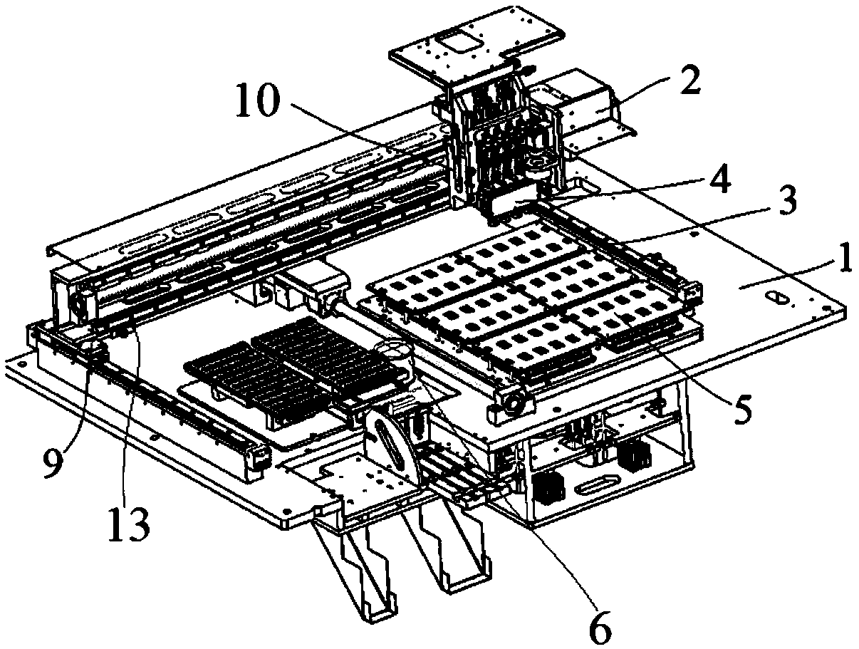
[0042] Embodiment 1: A chip programming machine capable of automatic loading and unloading, including a substrate 1, an X-axis driving mechanism 2, a Y-axis driving mechanism 3, a material suction mechanism 4 and a programming mechanism 5, and the Y-axis driving mechanism 3 is set On the upper surface of the substrate 1, the X-axis driving mechanism 2 is installed and connected with the Y-axis driving mechanism 3 through several XY connecting blocks 9 and can reciprocate in the Y-axis direction, and the suction mechanism 4 is movably installed through the XZ connecting blocks 10 On the X-axis drive mechanism 2 and can reciprocate along the X-axis direction, the burning mechanism 5 is installed on the substrate 1 and located below the suction mechanism 4;

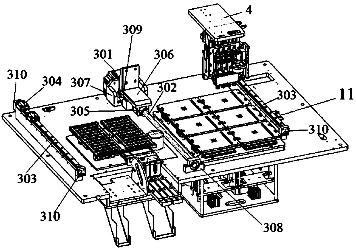
[0043] The Y-axis drive mechanism 3 further includes a Y-axis motor 301, a Y-axis screw 302 connected to the Y-axis motor 301, at least one Y-axis slide rail 303, and several Y-axis sliders movably mounted on the Y-axis slide...

Embodiment 2

[0054] Embodiment 2: A chip programming machine capable of automatic loading and unloading, including a substrate 1, an X-axis driving mechanism 2, a Y-axis driving mechanism 3, a suction mechanism 4 and a programming mechanism 5, and the Y-axis driving mechanism 3 is set On the upper surface of the substrate 1, the X-axis driving mechanism 2 is installed and connected with the Y-axis driving mechanism 3 through several XY connecting blocks 9 and can reciprocate in the Y-axis direction, and the suction mechanism 4 is movably installed through the XZ connecting blocks 10 On the X-axis drive mechanism 2 and can reciprocate along the X-axis direction, the burning mechanism 5 is installed on the substrate 1 and located below the suction mechanism 4;

[0055] The Y-axis drive mechanism 3 further includes a Y-axis motor 301, a Y-axis screw 302 connected to the Y-axis motor 301, at least one Y-axis slide rail 303, and several Y-axis sliders movably mounted on the Y-axis slide rail 303...


PUM


Abstract

The invention discloses a chip recording machine capable of automatically feeding and blanking. The device comprises a substrate, an X-axis driving mechanism, a Y-axis driving mechanism, a material suction mechanism and a recording mechanism. The Y-axis driving mechanism is arranged on an upper surface of the substrate. The X-axis driving mechanism is installed and connected with the Y-axis driving mechanism through a plurality of XY connecting blocks and can reciprocate in a Y-axis direction. A limiting support is also arranged. The limiting support is fixedly installed at a lower portion ofa front side surface of an installation plate. Several suction rods penetrate through the limiting support. The suction rods are connected with an upper plate of the limiting support through a drivingspline, the suction rods are connected with an installation portion of a corner installation plate through a driven spline, and the driving spline and the driven spline comprise cylindrical shells and at least two rows of balls vertically arranged on inner walls of the cylindrical shells. In the invention, automatic operation of a whole process of chip feeding, recording and blanking in a chip recording process is realized, precision is high, cyclic operation can be realized, and the precision, efficiency and an automation degree of chip recording are improved.

Description

technical field [0001] The invention relates to the technical field of chip programming, in particular to a chip programming machine capable of automatic loading and unloading. Background technique [0002] Chips are currently more commonly used electronic components in the electronics industry, and there are multiple production processes for them. Burning is one of the processes in chip manufacturing. When burning, it is necessary to control the burning point. Therefore, in the process of chip burning, there is a high requirement for the position accuracy of the chip placement. Existing chip programming is done manually or by a programming device, but the structure of the current chip programming device is relatively complicated and there are many processes, and still requires more manpower to participate, and the work efficiency is low. Contents of the invention [0003] The object of the present invention is to provide a chip programming machine capable of automatic lo...

Claims


Application Information

Patent Timeline
Patent Type & Authority Applications(China)
IPC IPC(8): H01L21/677
CPCG06F8/654
Inventor 桂义勇曹杰
Owner 苏州永测电子有限公司
Why Eureka
Try Eureka