
Dust collector

A vacuum cleaner and air-dust technology, applied in the field of air purification, can solve problems such as poor dust fall effect and achieve the best dust fall effect

Pending Publication Date: 2020-01-24
GREE ELECTRIC APPLIANCES INC
View PDF0 Cites 1 Cited by
  • Summary
  • Abstract
  • Description
  • Claims
  • Application Information

AI Technical Summary

Problems solved by technology

[0005] Based on this, it is necessary to provide a vacuum cleaner with better dust removal effect to solve the problem of poor dust removal effect of traditional vacuum cleaners.

Method used


Image

  • Dust collector
  • Dust collector
  • Dust collector

Examples


Embodiment Construction

[0033] In order to facilitate the understanding of the present invention, the present invention will be described more fully below with reference to the associated drawings. Preferred embodiments of the invention are shown in the accompanying drawings. However, the present invention can be embodied in many different forms and is not limited to the embodiments described herein. On the contrary, these embodiments are provided to make the understanding of the disclosure of the present invention more thorough and comprehensive.

[0034] It should be noted that when an element is referred to as being “fixed” to another element, it can be directly on the other element or there can also be an intervening element. When an element is referred to as being "connected to" another element, it can be directly connected to the other element or intervening elements may also be present. The terms "vertical," "horizontal," "left," "right," and similar expressions are used herein for purposes ...


PUM


Abstract

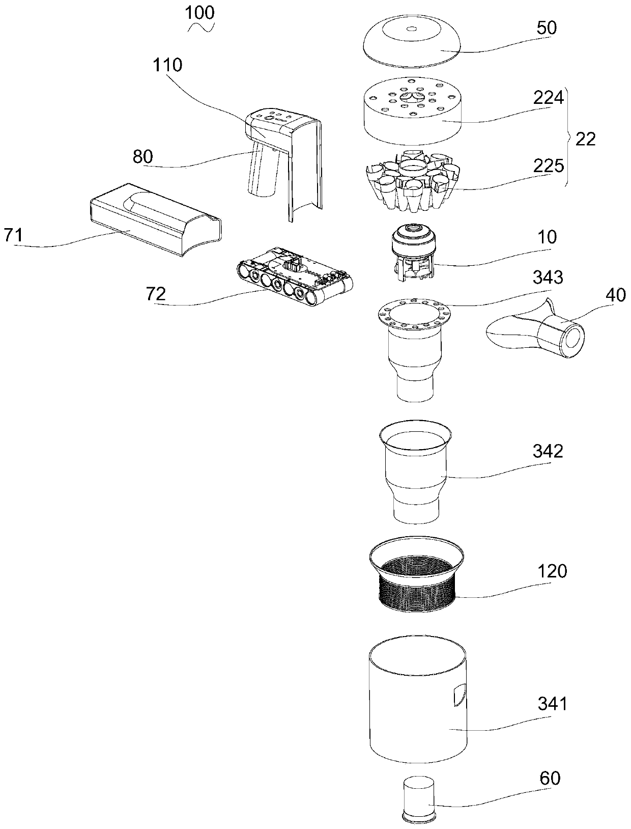
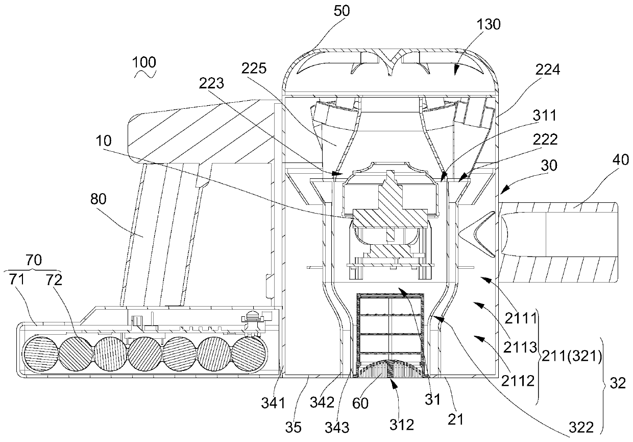
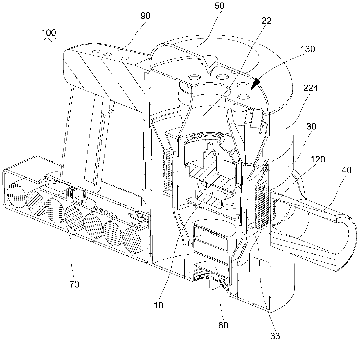
The invention relates to a dust collector which comprises a dust collection mechanism, a gas-dust separation mechanism and a gas generation mechanism, wherein the interior of the dust collection mechanism is hollow and is provided with a gas flow cavity with a gas suction hole and a gas exhaust hole; the interior of the dust collection mechanism is further provided with a dust collection cavity formed outside the gas flow cavity in a surrounding manner; the gas-dust separation mechanism is used for separating gas and dust, the dust formed after separation is deposited in the dust collection cavity, and the gas formed after separation flows to the gas suction hole; the gas generation mechanism is at least partially assembled in the gas flow cavity and is used for providing power for the gasto flow in the dust collector; the dust collection cavity and the gas flow cavity have a common wall; and the gas generation mechanism abuts against the common wall to transmit vibration to the common wall. When the gas generation mechanism works, the vibration of the gas generation mechanism is transmitted to the common wall, and the common wall vibrates together with the gas generation mechanism; and due to the fact that the common wall is used as the cavity wall of the dust collection cavity, the dust deposited on the wall surface of the dust collection cavity is separated from the wall surface to be deposited at the bottom of the dust collection cavity under the vibration action, and the relatively good dust falling effect is achieved.

Description

technical field [0001] The invention relates to the technical field of air purification, in particular to a vacuum cleaner. Background technique [0002] With the development of the economy and the progress of the society, people are increasingly pursuing the quality of life, and the cleanliness of the environment, as an important indicator for evaluating the quality of life, has attracted increasing attention. In order to improve the cleanliness of the environment, vacuum cleaners came into being. [0003] The vacuum cleaner mainly includes a power supply mechanism, a gas generating mechanism, a gas-dust separation mechanism and a dust collection mechanism. The dust collecting mechanism is used to collect the dust formed after gas-dust separation. [0004] However, in traditional vacuum cleaners, the dust formed after the separation of air and dust is easy to deposit on the wall of the dust collection mechanism, and the dust removal effect is not good. Contents of the i...

Claims


Application Information

Patent Timeline
Patent Type & Authority Applications(China)
IPC IPC(8): A47L5/12A47L9/00A47L9/16
CPCA47L5/12A47L9/0081A47L9/1625
Inventor 李锦坤
Owner GREE ELECTRIC APPLIANCES INC
Learn More