
Filter powder spraying device

A filter and powder spraying technology, which is applied in spraying devices, spray booths, etc., can solve the problem of low filter powder spraying efficiency

Active Publication Date: 2020-01-24
SIXIAN TENGMA AUTO PARTS CO LTD
View PDF5 Cites 0 Cited by
  • Summary
  • Abstract
  • Description
  • Claims
  • Application Information

AI Technical Summary

Problems solved by technology

[0003] The technical problem to be solved by the present invention is: the technical problem of low dusting efficiency of the filter in the prior art

Method used

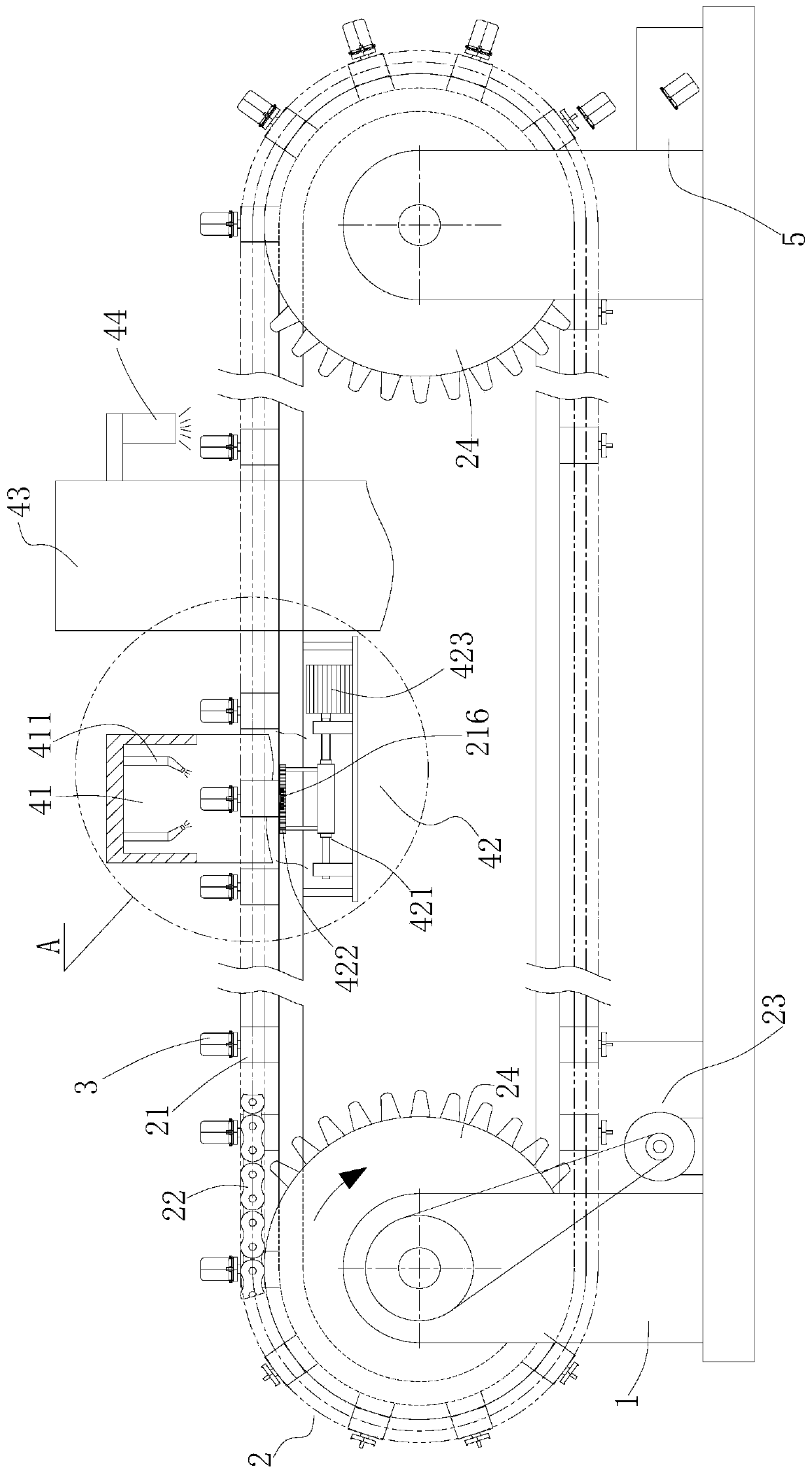

Image

  • Filter powder spraying device
  • Filter powder spraying device
  • Filter powder spraying device

Examples


Embodiment Construction

[0032] In order to make the purpose, technical solutions and advantages of the embodiments of the present invention clearer, the technical solutions in the embodiments of the present invention will be clearly and completely described below in conjunction with the embodiments of the present invention. Obviously, the described embodiments are part of the present invention Examples, not all examples. Based on the embodiments of the present invention, all other embodiments obtained by persons of ordinary skill in the art without creative efforts fall within the protection scope of the present invention.

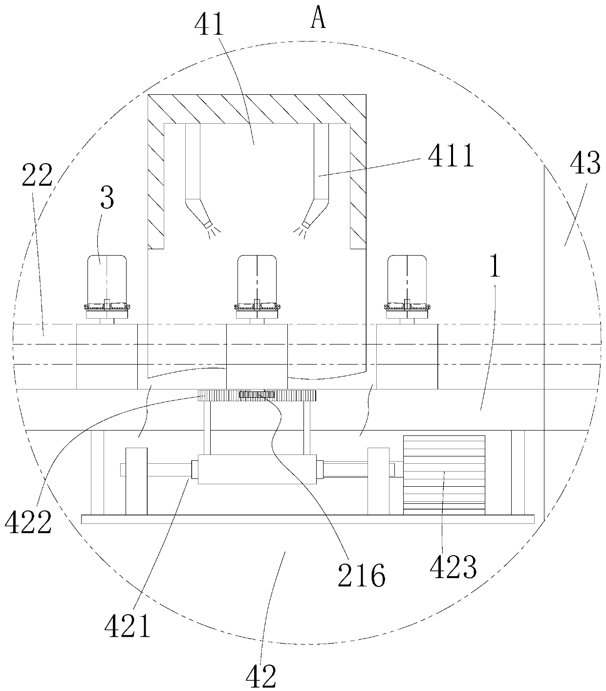
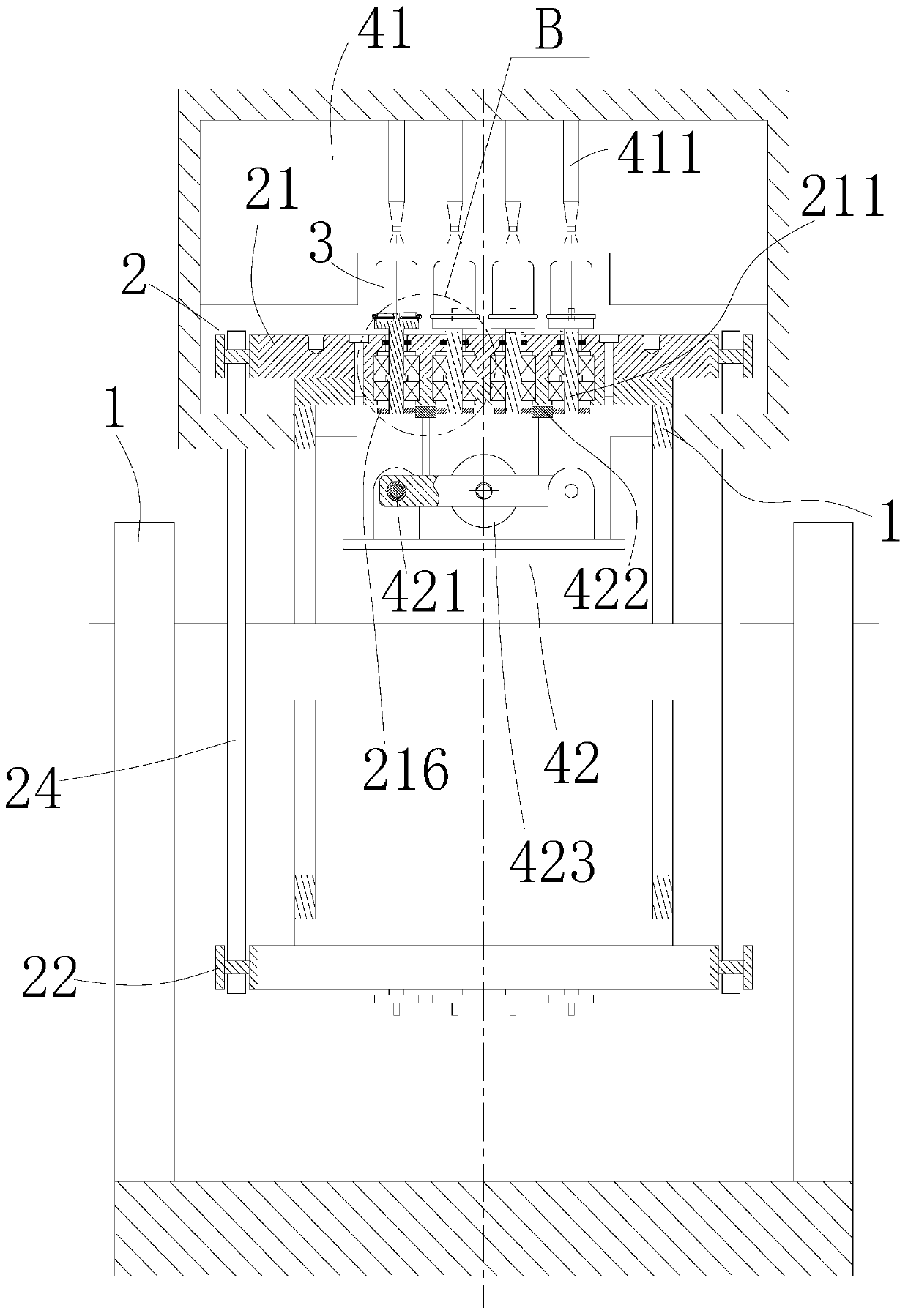
[0033] Such as figure 1 As shown, a filter powder spraying device includes a frame 1, a transmission mechanism 2, a filter 3, a powder spray chamber 41, a reciprocating drive mechanism 42, an oven 43, a cooling mechanism 44, a storage basket 5, and a control unit .

[0034] In this embodiment, the main function of the frame 1 is to provide installation positions for the rest of...


PUM


Abstract

The invention relates to the field of filter production, in particular to a filter powder spraying device. The device comprises a rack, a conveying mechanism, filters, a powder spraying chamber, a reciprocating driving mechanism, an oven, a cooling mechanism and a control unit. The filters are conveyed backwards under the action of the conveying mechanism, baked in the oven after powder spraying of the powder spraying chamber and then cooled through the cooling mechanism, so that membranes are formed. The device has the advantages that powder is uniformly sprayed on the surfaces of the filters, and meanwhile, the more the filters subjected to powder spraying every time is, the higher the overall powder spraying and membrane forming efficiency is.

Description

technical field [0001] The invention relates to the field of filter production, in particular to a filter powder spraying device. Background technique [0002] A filter refers to an accessory that filters impurities or gases through filter paper. Generally refers to the car filter, which is an accessory of the engine. In the production process of the filter, for the sake of appearance and anti-corrosion, it is necessary to spray powder and bake on the shell of the filter to form a dense film and protect the filter, such as the Chinese utility model with the application number CN201520988845.6 The patent discloses a dusting assembly line for filters, which firstly places the shell of the filter on the mould, starts the first motor, and makes the sprocket drive the chain to move, the chain drives the mould, and the mould carries the The filter housing moves to the powder spray booth. When the first gear meshes with the second gear, the first motor stops working, the second ...

Claims


Application Information

Patent Timeline
Patent Type & Authority Applications(China)
IPC IPC(8): B05B16/20B05B13/02
CPCB05B16/20B05B13/0235B05B16/95
Inventor 马训江张海波
Owner SIXIAN TENGMA AUTO PARTS CO LTD
Learn More