
Hydraulic oil tank and vehicle

A hydraulic oil tank and box body technology, which is applied in the direction of oil supply tank devices and mechanical equipment, can solve the problems that the hydraulic oil tank cannot meet the layout requirements and use requirements of the electric drive chassis, so as to save refueling space, facilitate the layout of the whole vehicle, and ensure The effect of pressure balance

Inactive Publication Date: 2020-01-24
SPECIAL VEHICLE TECH CENT OF HUBEI AEROSPACE TECH RES INST
View PDF6 Cites 0 Cited by
  • Summary
  • Abstract
  • Description
  • Claims
  • Application Information

AI Technical Summary

Problems solved by technology

[0004] The invention provides a hydraulic oil tank and a vehicle, which solves or partially solves the technical problem that the hydraulic oil tank in the prior art cannot meet the layout and use requirements of the electric drive chassis

Method used


Image

  • Hydraulic oil tank and vehicle
  • Hydraulic oil tank and vehicle
  • Hydraulic oil tank and vehicle

Examples


Embodiment Construction

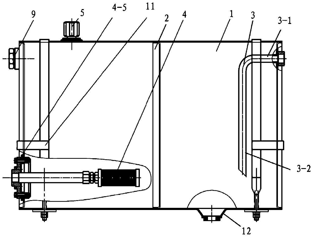
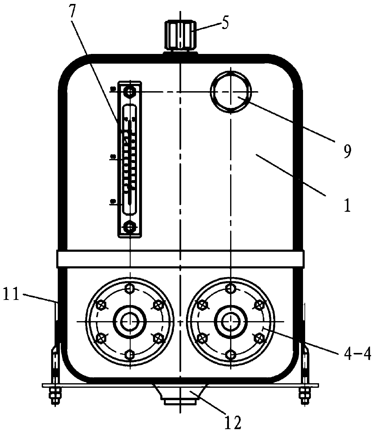
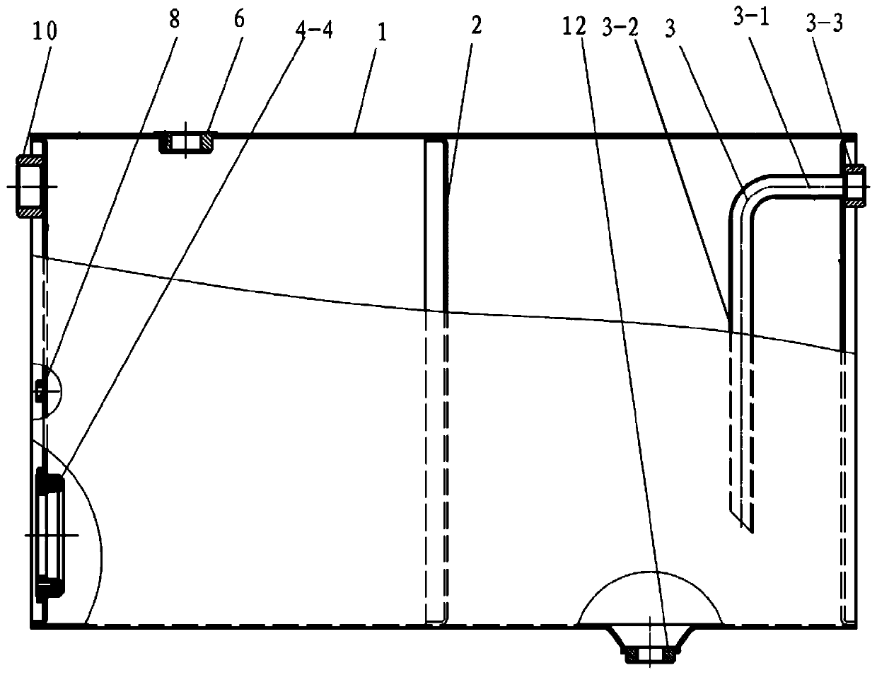
[0023] see Figure 1-4 , A hydraulic oil tank provided by an embodiment of the present invention includes: a tank body 1 and a partition 2 .

[0024] The partition plate 2 is fixedly arranged in the box body 1 and divides the box body 1 into a first cavity and a second cavity. The partition plate 2 is provided with a plurality of through holes.

[0025] The upper part of the first side of the box body 1 is provided with an oil filling port, and the lower part of the first side of the box body 1 is provided with an oil suction port, and both the oil filling port and the oil suction port communicate with the first cavity.

[0026] An oil return port is opened on the upper part of the second side of the case body 1, and the oil return port communicates with the second cavity, and the first side of the case body 1 is opposite to the second side of the case body.

[0027] The top of the box body 1 is provided with an air vent.

[0028] Specific embodiments of the present applicat...


PUM


Abstract

The invention discloses a hydraulic oil tank and a vehicle, and belongs to the technical field of electrically driving chassis. The hydraulic oil tank comprises a tank body and a partition plate, wherein the partition plate is fixedly arranged in the tank body, and divides the tank body into a first cavity and a second cavity; a plurality of through holes are formed in the partition plate; an oilfilling opening is formed in the upper part on the first side of the tank body; an oil suction opening is formed in the lower part on the first side of the tank body; both the oil filling opening andthe oil suction opening are communicated with the first cavity; an oil return opening is formed in the upper part on the second side of the tank body, and is communicated with the second cavity; the first side of the tank body is opposite to the second side of the tank body; and a vent is formed in the top of the tank body. The hydraulic oil tank and the vehicle of the invention can meet the arrangement requirements of the electrically driving chassis and the hydraulic oil volume requirements required for realizing the functions of hydraulic systems.

Description

technical field [0001] The invention relates to the technical field of electric drive chassis, in particular to a hydraulic oil tank and a vehicle. Background technique [0002] At present, military super-heavy off-road chassis usually adopt hydraulic power steering technology. In recent years, with the upgrading of domestic weapon systems, more and more vehicle-mounted weapon systems require the chassis to have functions such as height adjustment, and the large-stroke oil-pneumatic suspension technology has been widely used. Whether it is hydraulic power steering grouping technology or large-stroke oil-pneumatic suspension technology, hydraulic oil is used as the working medium to realize its functions. In order to realize these functions, it is usually necessary to equip a large-volume hydraulic oil tank on the chassis to provide enough hydraulic oil for the normal operation of the system. [0003] However, due to the large difference in the overall layout of the electri...

Claims


Application Information

Patent Timeline
Patent Type & Authority Applications(China)
IPC IPC(8): F15B1/26
CPCF15B1/26
Inventor 谈伟李雪婧何建国吴东
Owner SPECIAL VEHICLE TECH CENT OF HUBEI AEROSPACE TECH RES INST
Learn More