

Powder preheating device for SLM equipment and working method thereof
A technology of preheating device and heating device, which is applied in the field of additive manufacturing, can solve the problems of large temperature transfer gradient, temperature rise, and inability to guarantee the temperature consistency of the surrounding environment, so as to achieve good heat preservation effect, stable preheating temperature, and eliminate Caton effect
Pending Publication Date: 2019-07-05
XIAN BRIGHT ADDTIVE TECH CO LTD
View PDF6 Cites 4 Cited by
- Summary
- Abstract
- Description
- Claims
- Application Information
AI Technical Summary
Problems solved by technology
[0003] As SLM equipment prints large parts, the substrate size becomes larger and larger, and the heat required increases accordingly. The heating current of the electric heating method is also increasing, and it will be difficult to design wiring on the heating plate. There is a big security risk
Due to the existence of voltage and current in electric heating, risks and problems such as short circuit and metal powder explosion are prone to occur in dusty environment
Since electric heating reaches the powder layer indirectly through heat conduction, the heating plate is used as a heat source to transfer heat from bottom to top, and the gradient of temperature transfer is large, which cannot guarantee the consistency of the surrounding environment temperature, and the thickness of the substrate is different and deviates. , these factors will inevitably lead to a large temperature difference on the surface of the substrate, thus affecting the quality of part printing
Using the heating plate as the heat source, when the preheating temperature is high, it takes a long time to heat up, resulting in the continuous rise of the ambient temperature, thermal expansion and deformation of the heating plate, and the subsequent rise and fall of the substrate are prone to jamming, resulting in printing interruptions question
The electric heating cannot be turned on all the time. In order to keep the preheating temperature unchanged, it cannot be done accurately. When the temperature is higher than the preheating temperature, the heating is stopped. When the temperature is lower than the preheating temperature, the heating is turned on. Therefore, the preheating temperature is at a certain Changes within the range, can not guarantee a constant temperature
Method used
View moreImage
Smart ImageViewing Examples

Examples
Embodiment 1
[0050] Take the preheating of the heating channel 13 in the heating plate of the equipment as an example, the preheating temperature is 100°C, and the working process is as follows:
Login to View More PUM
 Abstract
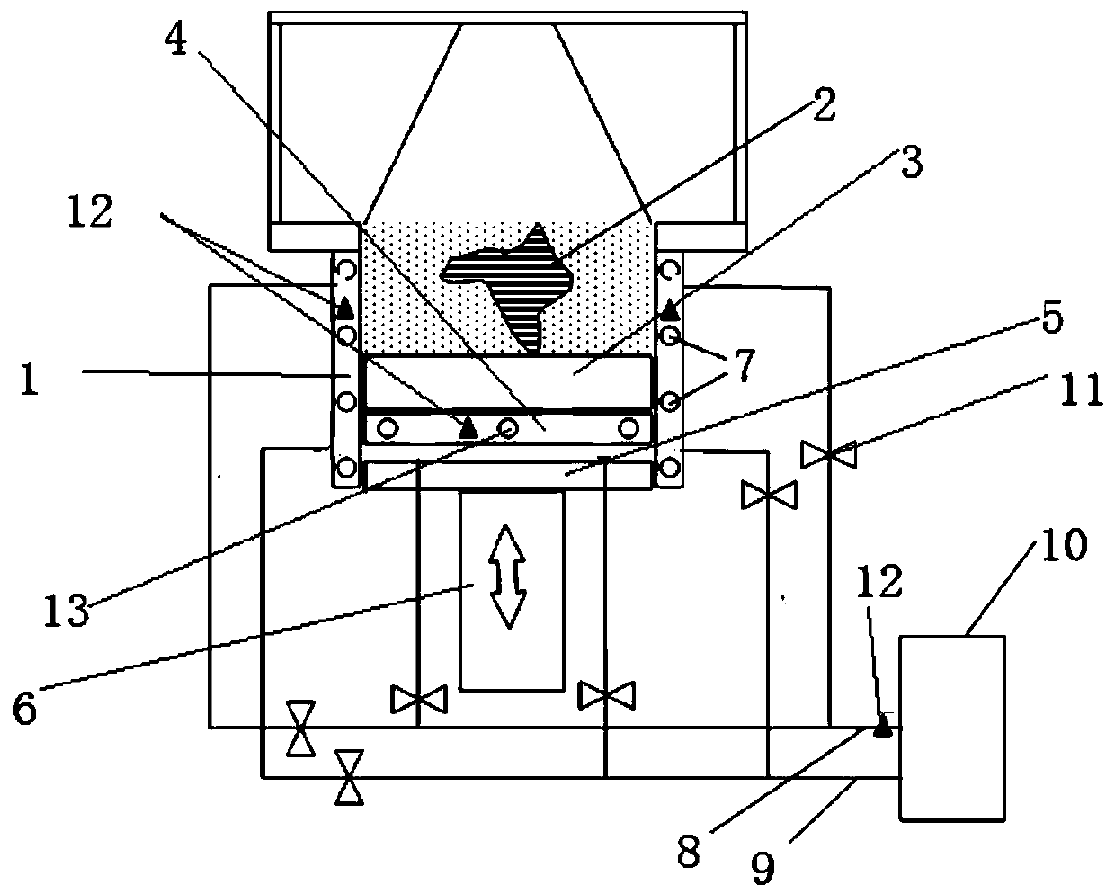
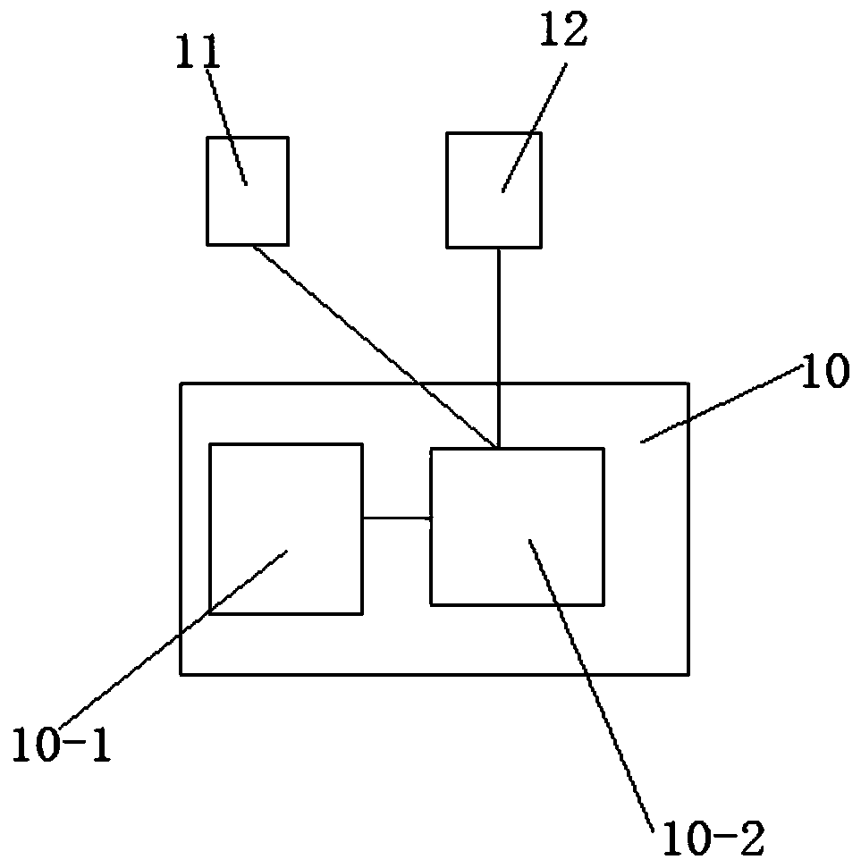
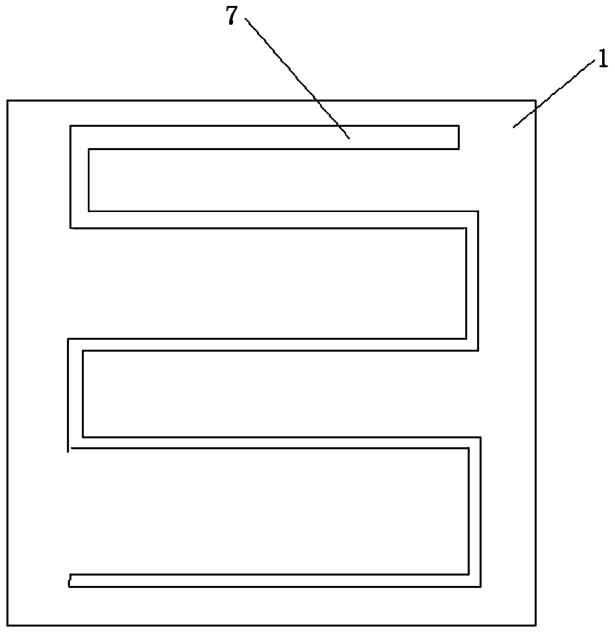
The invention discloses a powder preheating device for SLM equipment. The powder preheating device for the SLM equipment comprises a forming cylinder, a Z-axis lifting forming frame is arranged in theforming cylinder, a heat insulation plate is arranged on the upper surface of the Z-axis lifting forming frame, a heating plate is arranged on the upper surface of the heat insulation plate, and a substrate is arranged on the upper surface of the heating plate; and the powder preheating device for the SLM equipment further comprises a liquid heating temperature control device, a forming cylinderinner flow channel is embedded into the side wall of the forming cylinder, the two ends of the forming cylinder inner flow channel are connected with an inlet and an outlet of the liquid heating temperature control device, a heating flow channel is embedded into the substrate or the heating plate, and the two ends of the heating flow channel are also connected with the inlet and the outlet of theliquid heating temperature control device. According to the powder preheating device for the SLM equipment, a liquid heating mode is adopted, safe constant-temperature heating can be achieved, and a short circuit and the risk that metal powder is detonated to cause explosion are avoided. The invention further discloses a working method of the powder preheating device.
Description
technical field [0001] The invention belongs to the technical field of additive manufacturing, and relates to a powder preheating device for SLM equipment, and also relates to a working method of the powder preheating device. Background technique [0002] At present, the way SLM equipment preheats the powder is to generate heat through electricity, and then achieve the purpose of preheating the powder layer. Firstly, make grooves for wiring on the heating plate, and the distribution of the grooves should be evenly distributed on the heating plate, in order to achieve uniform heating of the entire heating plate. The groove is opened on the back of the heating plate because the wires are routed from the Z-axis forming cylinder below, and the base material is above. Cover the contact with copper after the trenches are routed. Copper has good thermal conductivity and can transfer heat quickly. Heat transfer Firstly, heat is generated by resistance, and then dissipated by coppe...
Claims
Login to View More Application Information
Patent Timeline
 Patent Type & AuthorityApplications(China)
IPC IPC(8): B22F3/105B33Y30/00B33Y50/02
CPCB33Y30/00B33Y50/02B22F10/00B22F12/90B22F10/28B22F12/30Y02P10/25
Inventor杨东辉赵彪
OwnerXIAN BRIGHT ADDTIVE TECH CO LTD