Hydraulic system of crane and working method

A hydraulic system and working method technology, applied in the direction of cranes, fluid pressure actuation system safety, fluid pressure actuation system components, etc., can solve the problems of difficult work of the main circuit system, low energy utilization rate, high temperature of hydraulic pumps, etc. Achieve the effect of improving the service life, improving the utilization rate of energy and reducing the loss of energy

Pending Publication Date: 2019-02-01
SOUTH CHINA MARINE MACHINERY
View PDF0 Cites 5 Cited by
  • Summary
  • Abstract
  • Description
  • Claims
  • Application Information

AI Technical Summary

Problems solved by technology

[0004] Most of the existing hydraulic systems used on cranes are open systems, and the defect of the open system is that the utilization rate of energy is low
For cranes, safety performance is very important. In this way, if only the main circuit system is used, once the main circuit system fails, the entire crane will fail, which may cause major safety accidents
In addition, for a closed hydraulic system, since the hydraulic oil circulates in the main circuit system, the temperature of the hydraulic pump will be relatively high. If it is not cooled in time, it will easily cause the hydraulic pump to fail.
In addition, with a closed hydraulic system, there will always be loss of hydraulic oil in the main circuit system. If the oil is not replenished in time, the main circuit system will be difficult to work normally.

Method used


Image

  • Hydraulic system of crane and working method
  • Hydraulic system of crane and working method
  • Hydraulic system of crane and working method

Examples


Embodiment Construction

[0040] The present invention will be described in further detail below in conjunction with the accompanying drawings and specific embodiments.

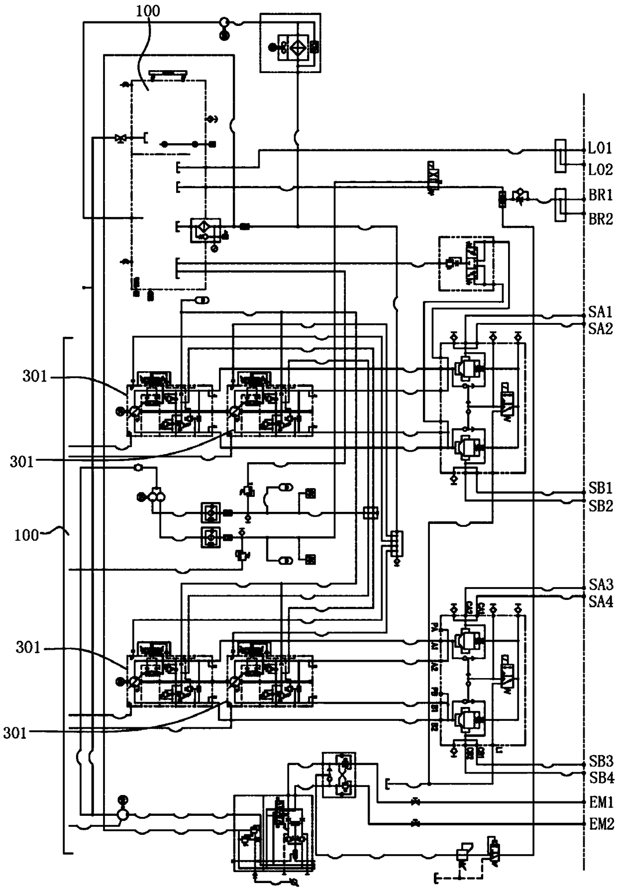
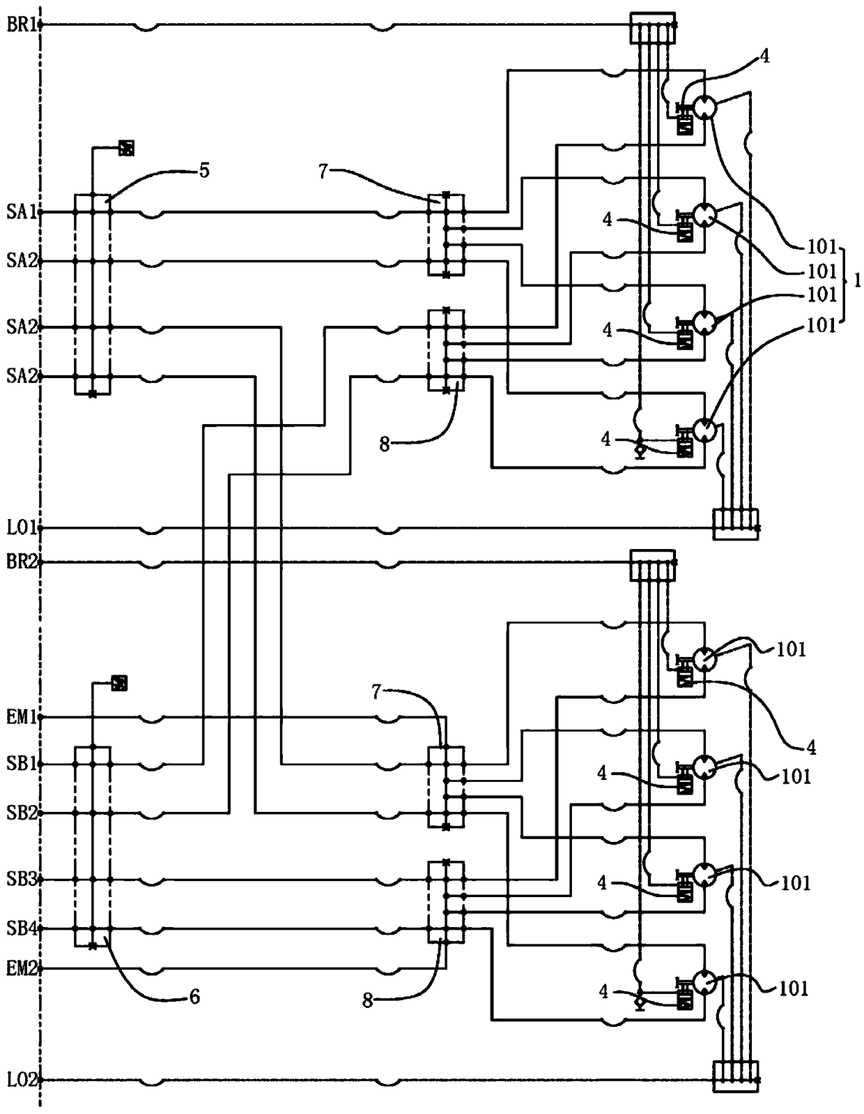
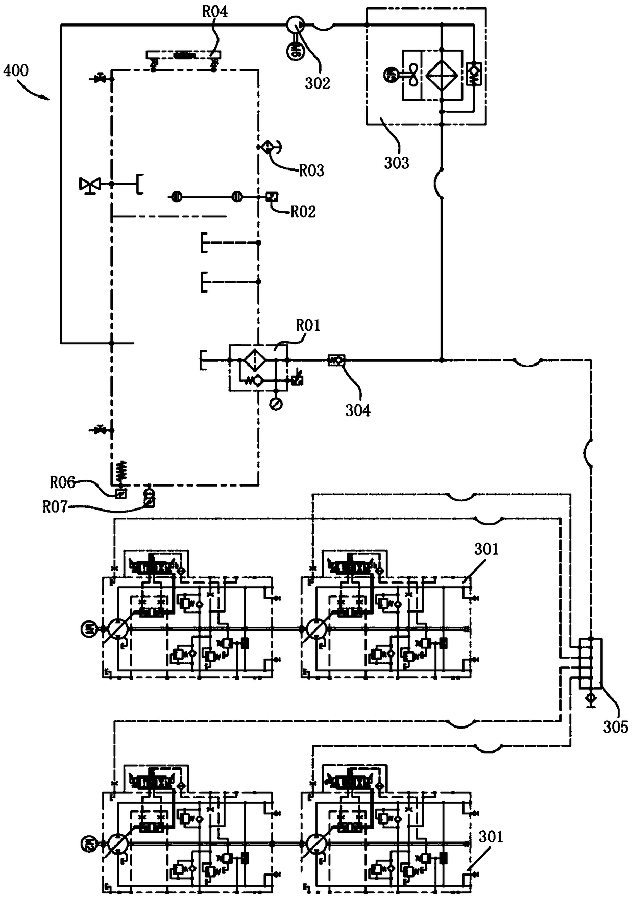
[0041] Such as Figure 1 to Figure 6 As shown, a crane hydraulic system includes an oil tank 100, a slewing system 200 for driving a slewing platform, a brake system 300, a cooling system 400 for lowering oil temperature, an oil replenishment system 500 for replenishing oil, and a Hydraulic emergency system 600 activated in case of failure.

[0042] The slewing system 200, the cooling system 400, and the oil supply system 500 are relatively independent, have little mutual influence, can work independently, and improve the stability of the hydraulic system. The slewing system 200 and the braking system 300 are related to each other, guarantee each other, and improve the safety performance of the hydraulic system. Equipped with a hydraulic emergency system to further improve the safety performance of the hydraulic system.

[0043] Th...


PUM


Abstract

The invention relates to a crane, and particularly relates to a hydraulic system of a crane for vessel operation and a working method. The hydraulic system of the crane comprises a fuel tank, a gyrating system for driving a gyrating platform, a brake system, a cooling system for decreasing the oil temperature, an oil supplementing system for supplementing oil, and an emergency gyrating system which is started in case of fault. According to the hydraulic system of the crane and the working method, the gyrating system is a closed hydraulic system, so that the energy utilization rate is high; theoil supplementing system is arranged and used for supplementing consumed hydraulic oil of the closed hydraulic system; a brake shuttle valve is arranged in the brake system; a normal brake system isconnected to a brake oil channel of a hydraulic emergency system, thus realizing a two-input and one-output brake system, and as a result, the safety is improved; the cooling system is arranged and used for cooling a hydraulic pump set, so that the probability of failure of the hydraulic pump set can be reduced; and the hydraulic emergency system is provided, so that the safety of the crane is improved.

Description

technical field [0001] The invention relates to a crane, especially a crane hydraulic system and working method for ship operation. Background technique [0002] At present, the slewing crane around the pile is usually installed on the legs of various offshore platforms. It is widely used because of its small platform space, compact structure, large lifting capacity, and long lifting radius. [0003] The pile-encircling slewing crane mainly includes a base, a slewing bearing, a slewing platform, a lifting mechanism and a hydraulic system. There is enough space in the middle of the slewing platform to allow the legs to pass therethrough. In a large pile-wound slewing crane, the slewing platform and the base are connected by a slewing bearing. The slewing bearing has three seat rings. Steel balls and spacers can be directly discharged into the upper and lower raceways. The upper and lower rows of steel balls with different diameters. The bearing angles of the upper and lowe...

Claims


Application Information

Patent Timeline
Patent Type & Authority Applications(China)
IPC IPC(8): B66C13/20B66C23/86F15B1/02F15B11/17F15B13/06F15B20/00F15B21/041F15B21/0423F16D65/14F16D121/02F16D125/02
CPCB66C13/20B66C23/86F15B1/024F15B11/17F15B13/06F15B20/004F15B21/041F15B21/042F15B2211/20576F15B2211/212F15B2211/505F15B2211/615F15B2211/62F15B2211/8633F16D65/14F16D2121/02F16D2125/02
Inventor 陈懿王江梁兆环安万平
Owner SOUTH CHINA MARINE MACHINERY
Why Eureka
Try Eureka