Gearbox oil return structure

A gearbox and oil return technology, which is applied in gear lubrication/cooling, belt/chain/gear, fixed filter elements, etc., can solve problems such as oil return blockage, avoid blockage, improve filtering effect, and ensure oil return cooling effect

Active Publication Date: 2020-01-24
江苏蓝鹰液压科技有限公司
View PDF6 Cites 0 Cited by
  • Summary
  • Abstract
  • Description
  • Claims
  • Application Information

AI Technical Summary

Problems solved by technology

[0004] However, it improves the flow area and dirt-holding capacity of the filter to a certain extent, but there is still a technical problem of oil return clogging. For this reason, the inventor has integrated various factors and proposed a gear box oil return structure.

Method used


Image

  • Gearbox oil return structure
  • Gearbox oil return structure

Examples


Embodiment 1

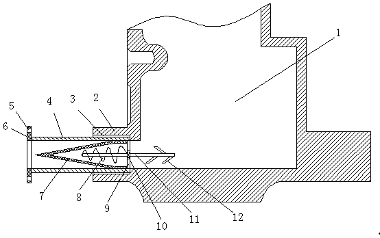
[0028] Embodiment 1, referring to the figure, an oil return structure of a gear box, including a box body 1, an oil return pipeline 4 is arranged at the bottom of the box body 1, and the oil return pipeline 4 is detachably sealed with the box body 1, and the oil return pipeline The pipeline 4 is provided with an oil-driven micro-power return oil disturbance filter mechanism.

[0029] When working, the micro-power oil return disturbance filter mechanism is driven by the oil return oil to perform disturbance filtration, which greatly improves the oil return filtration effect, effectively prevents the blockage of the oil return oil circuit, and facilitates the normal oil return circulation of the oil in the tank 1. Ensure the normal lubrication of the parts in the box body 1 and return the oil to cool down.

[0030] Wherein, the micro-power oil return disturbance filter mechanism includes a filter screen cylinder 7, the open end of the filter screen cylinder 7 is installed in the...

Embodiment 2

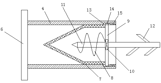
[0037] Embodiment two, refer to figure 2 ; The present embodiment increases the following technical features on the basis of Embodiment 1:

[0038] Among them, the grid frame 9 is elastically slidingly matched with the oil return pipeline 4; the filter screen cylinder 7 and the grid frame 9 can reciprocate at the end of the oil return pipeline 4, and the filter screen cylinder 7 and the grid frame 9 are pushed by the oil Reciprocating motion further improves the effect of too fast disturbance.

[0039] Wherein, the oil return pipeline 4 is provided with a chute 13 in the port close to the side of the box body 1, and the chute 13 is arranged symmetrically up and down along the port of the oil return pipeline 4, and the top and bottom of the grid frame 9 are respectively provided with sliders 14, The slider 14 is set in the chute 13, and the chute 13 is provided with a telescopic spring 15. One end of the telescopic spring 15 is fixedly connected with the slider 14, and the ot...


PUM


Abstract

The invention discloses a gearbox oil return structure. The gearbox oil return structure comprises a box body, wherein an oil return pipeline is arranged at the bottom of the box body; the oil returnpipeline and the box body are detachably assembled in a sealed mode; and a micro-power oil return disturbance filtering mechanism driven by oil liquid is arranged in the oil return pipeline. Accordingto the gearbox oil return structure, the micro-power oil return disturbance filtering mechanism is driven by the oil return oil liquid ingeniously, disturbance filtering is carried out, the oil return filtering effect is greatly improved, an oil return oil path is effectively prevented from being blocked, normal oil return circulation of the oil liquid in the box body is facilitated, and normal lubrication and oil return cooling of parts in the box body are guaranteed. According to the gearbox oil return structure, the oil liquid is further used for driving disturbance blades to rotate alongwith a disturbance shaft in the oil return process, so that the oil liquid is subjected to disturbance filtering in a filter screen cylinder, and the filtering effect is improved; and in addition, thedisturbance shaft extends into the box body and is subjected to disturbance operation at the communicating port of the box body and the oil return pipeline and the box body, so that the port positionof the oil return pipeline is prevented from being blocked, and the disturbance filtering effect is further improved.

Description

technical field [0001] The invention belongs to the technical field of gear boxes, in particular to an oil return structure of a gear box. Background technique [0002] The lubricating oil in the lubricating oil system of the transmission gearbox will inevitably be polluted, mainly including the wear and corrosion of the frictional counterpart, coking or sludge of the lubricating oil, sand and dust entering from the outside, and machine residues that are not cleaned cleanly, etc. Therefore, , The filter screen assembly is an essential part of the transmission gearbox lubricating oil system. At present, the filter screen used in a certain transmission gearbox is a conical grid type filter screen, which is directly installed in the oil discharge pipe of the gearbox, such as figure 1 , simple structure, convenient installation and maintenance, and can meet the use requirements in normal use of the product. However, when a certain part of the transmission gearbox is damaged an...

Claims


Application Information

Patent Timeline
Patent Type & Authority Applications(China)
IPC IPC(8): F16H57/04F16N39/06B01D29/35B01D29/94B01D33/03B01D33/76
CPCF16H57/0404F16H57/0423B01D29/35B01D29/94B01D33/0338B01D33/76
Inventor 张如林刘峰
Owner 江苏蓝鹰液压科技有限公司
Why Eureka
Try Eureka