Supercharge Your Innovation With Domain-Expert AI Agents!

Automatic sewage discharging device and control method thereof

An automatic sewage and sewage valve technology, applied in pipeline systems, mechanical equipment, gas/liquid distribution and storage, etc., can solve the problems of reduced use efficiency, single sewage method, and structural limitations of sewage devices, and achieve efficient installation and improve sewage. Efficiency, the effect of improving the efficiency of use

Pending Publication Date: 2020-01-24
RUINA INTELLIGENT EQUIP CO LTD
View PDF0 Cites 0 Cited by
  • Summary
  • Abstract
  • Description
  • Claims
  • Application Information

AI Technical Summary

Problems solved by technology

[0002] In the pipe network system, the sewage removal device is often used to discharge the sewage in the pipeline. The traditional sewage discharge method is single, and it cannot perform real-time and effective sewage discharge according to the sewage content in the pipeline. At the same time, the existing sewage discharge device is limited by the structure and is not suitable for The installation of various piping systems further reduces its efficiency

Method used


Image

  • Automatic sewage discharging device and control method thereof

Examples


Embodiment 1

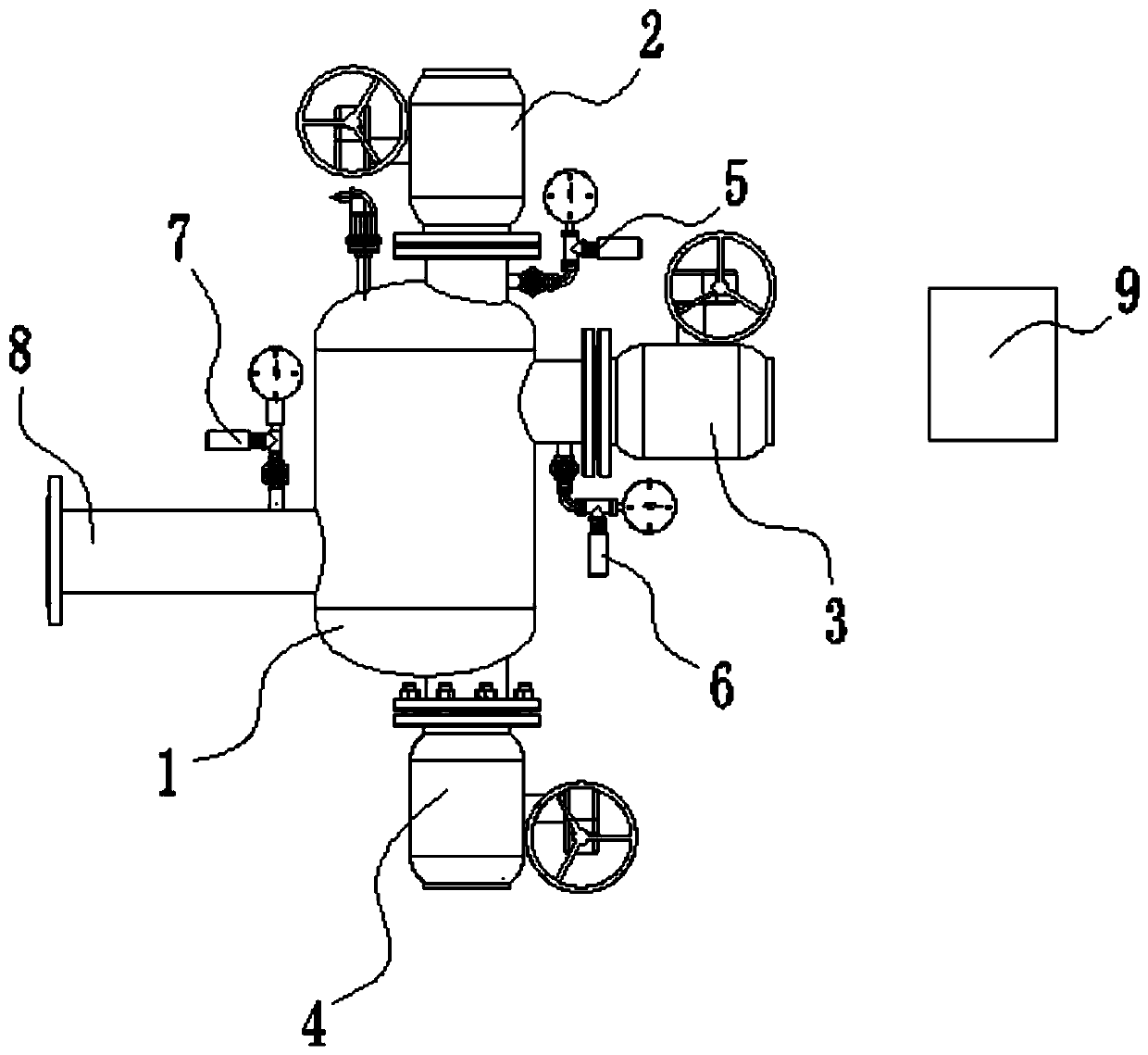
[0026] Any one of the electric control valve 2 or the electric control valve 3 is connected to the pipeline system, and the other electric control valve not connected to the pipeline system is closed. The pressure sensor 5 or the pressure sensor 6 detects the current water inlet pressure value, and at the same time detects the water pressure of the water pipe. 8, the water inlet pressure value and the water outlet pressure value are uploaded to the controller 9, and the controller 9 calculates the pressure difference. The controller 9 has a preset pressure difference value. When the pressure difference is greater than The preset pressure difference indicates that the pressure in the tank 1 is unbalanced due to more dirt at the port. At this time, the automatic sewage discharge program is entered. The automatic sewage discharge program is as follows:

[0027] First, close all the electric regulating valves through the controller 9, and then the controller 9 controls the opening ...

Embodiment 2

[0029] Both the electric regulating valve 2 and the electric regulating valve 3 are connected to the pipeline system, and the current water inlet pressure value is detected by the pressure sensor 5 and the pressure sensor 6, and the water outlet pressure value at the water pipe 8 is detected at the same time, and the water inlet pressure value and the water outlet pressure value are compared. The pressure value is uploaded to the controller 9, and the controller 9 calculates the pressure difference. The preset pressure difference is set in the controller 9. When the pressure difference of any group is greater than the preset pressure difference, it means that the tank In body 1, the pressure at the port is unbalanced due to more dirt. At this time, it enters the automatic sewage discharge procedure. The automatic sewage discharge procedure is as follows:

[0030] Firstly, the electric control valve 2 and the electric control valve 3 are closed by the controller 9, and then the ...


PUM


Abstract

The invention discloses an automatic sewage discharging device and a control method thereof. The automatic sewage discharging device comprises a tank body and a water outlet pipe mounted on one side of the tank body, wherein one or more water inlets are formed in the tank body; electric adjusting valves are mounted at the one or more water inlets; pressure sensors are mounted at the water outlet ends of the electric adjusting valves and on the water outlet pipe; a sewage discharging opening is formed in the bottom of the tank body; an electric control sewage discharging valve is mounted at thesewage discharging opening. According to the technical scheme, the sewage discharging device is efficiently mounted through a multi-inlet and one-outlet structural form, so that the device can be connected with various pipelines, and the use efficiency is effectively improved; meanwhile, the arranged pressure sensors can detect the water pressure change at the water outlet ends in real time, thesewage content in the device is reflected through the change of the pressure value, and the real-time online sewage discharging effect is realized by combining the opening and closing control of the valves, so that the sewage discharging efficiency is effectively improved.

Description

technical field [0001] The invention relates to the technical field of pipeline sewage discharge, in particular to an automatic sewage discharge device and a control method thereof. Background technique [0002] In the pipe network system, the sewage removal device is often used to discharge the sewage in the pipeline. The traditional sewage discharge method is single, and it cannot perform real-time and effective sewage discharge according to the sewage content in the pipeline. At the same time, the existing sewage discharge device is limited by the structure and is not suitable for The installation of a variety of piping systems further reduces its efficiency. Contents of the invention [0003] The object of the present invention is to provide an automatic sewage discharge device and its control method, so as to solve the problems raised in the above-mentioned background technology. [0004] In order to achieve the above object, the present invention provides the follow...

Claims


Application Information

Patent Timeline
IPC IPC(8): F17D5/00F17D3/01
CPCF17D3/01F17D5/00
Inventor 董君永张世钰唐宝洪赵娅玲朱天生孟祥斌王贺贺蔡先航
Owner RUINA INTELLIGENT EQUIP CO LTD
Features
  • R&D
  • Intellectual Property
  • Life Sciences
  • Materials
  • Tech Scout
  • Unparalleled Data Quality
  • Higher Quality Content
  • 60% Fewer Hallucinations
Learn More