Bus duct connector

A technology of busbar connectors and card slots, which is applied in the direction of fully enclosed busbar devices, can solve problems such as inconvenient operation, and achieve the effect of conductive connection

Inactive Publication Date: 2020-01-24
AMPHENOL PCD SHENZHEN
View PDF0 Cites 4 Cited by
  • Summary
  • Abstract
  • Description
  • Claims
  • Application Information

AI Technical Summary

Problems solved by technology

However, such a setting has disadvantages: during installation, the screw rod needs to be locked from the side, which is very inconvenient to operate, and sufficient operating space is required

Method used


Image

  • Bus duct connector
  • Bus duct connector
  • Bus duct connector

Examples


Embodiment Construction

[0036] Below, the present invention will be further described in conjunction with the accompanying drawings and specific implementation methods. It should be noted that, under the premise of not conflicting, the various embodiments described below or the technical features can be combined arbitrarily to form new embodiments. .

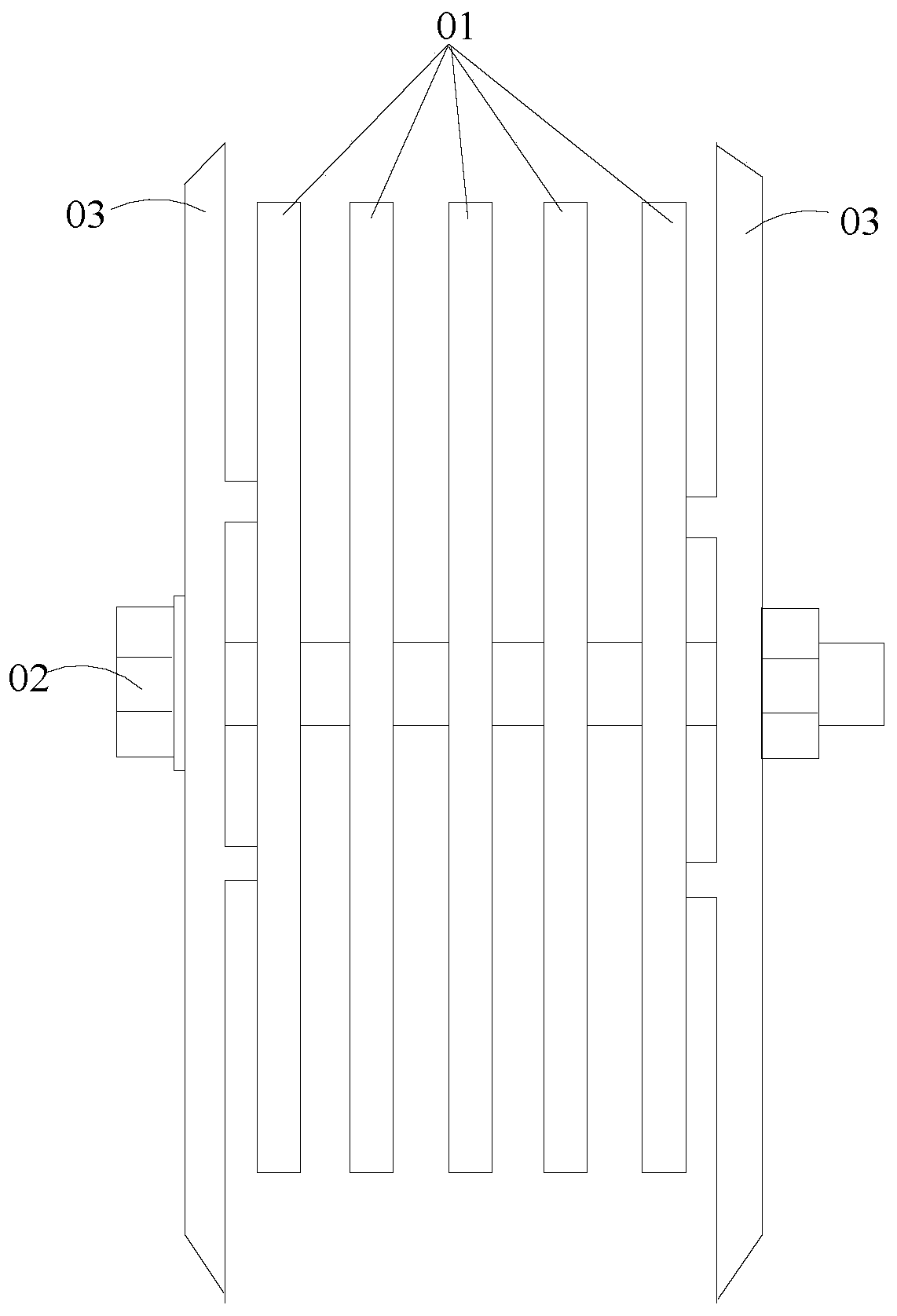
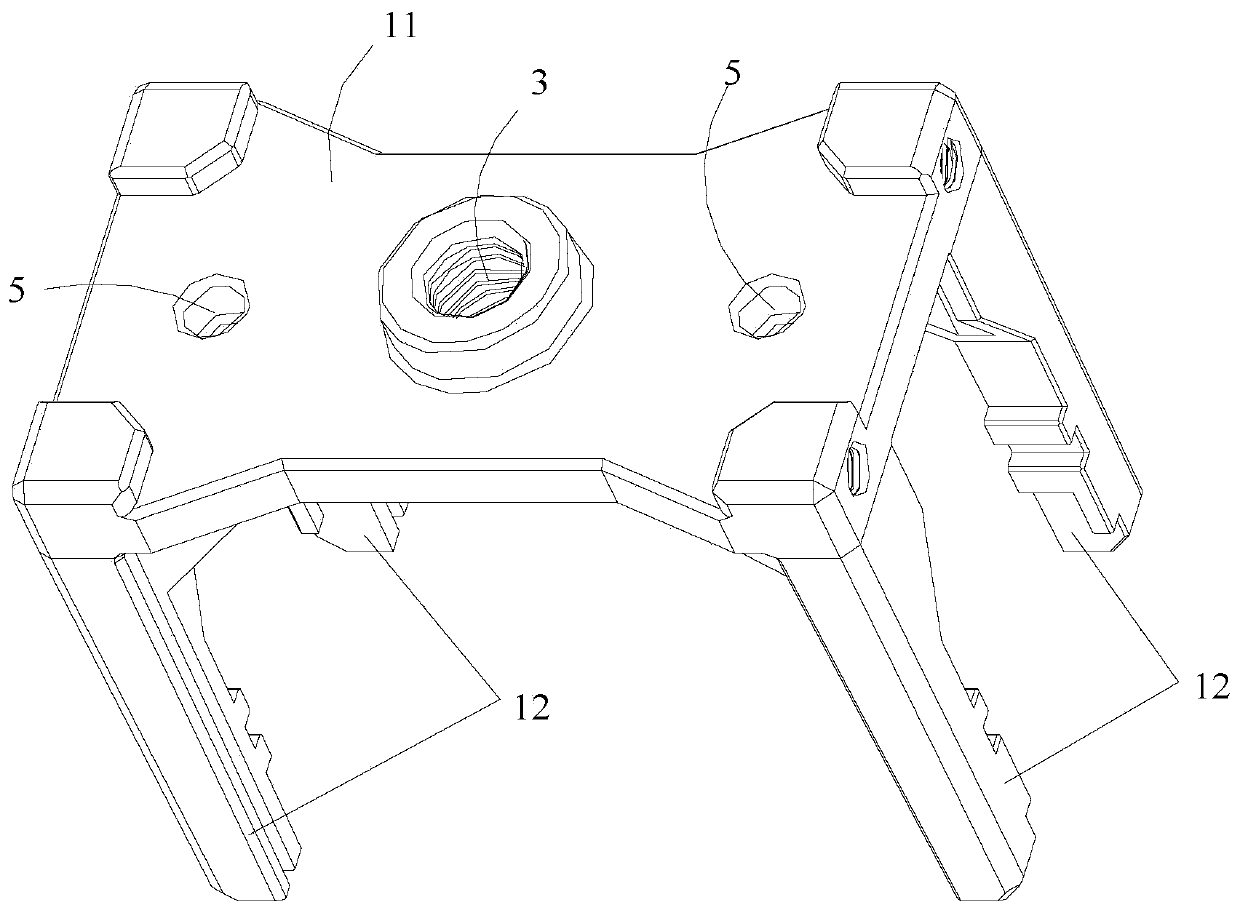
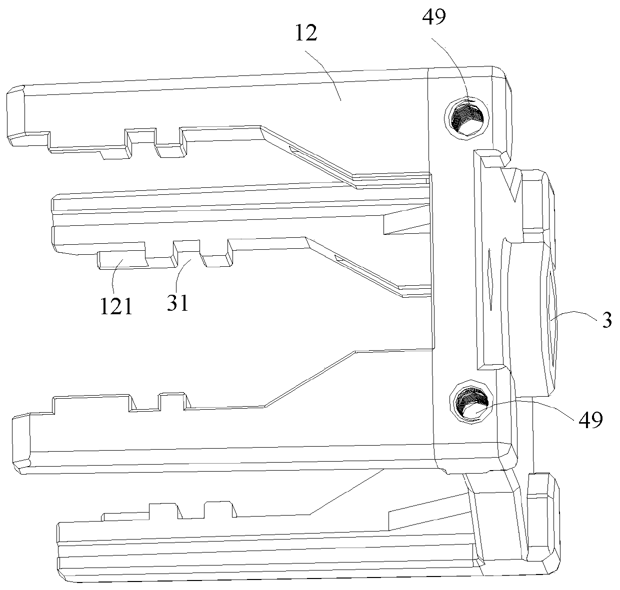
[0037] The busway connector provided by the present invention includes a bracket, a bead, a left slanting block, a right slanting block, a left shell and a right shell. Wherein, the left inclined block and the right inclined block are arranged in parallel, and the left shell and the right shell are arranged in parallel between the left inclined block and the right inclined block; several middle shells are arranged in parallel between the left shell and the right shell. Between the middle shell and the middle shell, and between the middle shell and the side shells, contact pieces and elastic spacers are arranged, and the contact pieces are used for cont...


PUM


Abstract

The invention provides a bus duct connector comprising a bracket, a pressing strip, a left inclined block, a right inclined block, a left shell and a right shell. The left shell and the right shell are arranged between the left inclined block and the right inclined block. A plurality of middle shells are arranged in parallel between the left shell and the right shell. Contact pieces and elastic spacers are arranged between the shells. The left side of the lower end of the pressing strip is provided with a first inclined plane. The right side of the lower end of the pressing strip is provided with a second inclined plane. The upper end of the left inclined block is provided with a third inclined plane. The upper end of the right inclined block is provided with a fourth inclined plane. The first inclined plane is in contact with the third inclined plane, and the second inclined plane is in contact with the fourth inclined plane. The left side of the lower end of the bracket and the leftinclined block are connected in a leftward and rightward movement way, and the right side of the lower end and the right inclined block are connected in a leftward and rightward movement way. The upper end of the bracket is provided with a downward pressing locking piece. The pressing strip is arranged between the lower pressing locking piece and the inclined block, and the lower pressing lockingpiece is used for driving the pressing strip to move downward so as to drive the left and right inclined blocks to move in the direction close to each other to compress the elastic spacers and enablethe contact pieces to contact with the bus duct copper bar.

Description

technical field [0001] The invention relates to the technical field of electric equipment, in particular to a bus duct connector. Background technique [0002] The busway is a closed metal device composed of copper and aluminum busbar columns, which is used to distribute large power to various components of the decentralized system. It has increasingly replaced wires and cables in indoor low-voltage power transmission trunk line projects. The bus duct connector is used to connect the front and rear bus ducts together to realize the transmission of current. Such as figure 1 As shown, the traditional busway connector is composed of several copper plates 01, screw 02 and two splints 03; the two splints 03 are arranged in parallel, and several copper plates 01 are arranged in parallel between the two splints 03, and then the screw 02 is used to connect them from the side. Pass through the middle of the splint 03 and the copper plate 01, so that the splint 03 and the copper pl...

Claims


Application Information

Patent Timeline
Patent Type & Authority Applications(China)
IPC IPC(8): H02G5/06
CPCH02G5/06
Inventor 于静黄宏图刘常明张营兵彭惟鹿
Owner AMPHENOL PCD SHENZHEN
Why Eureka
Try Eureka