
Guide rail type LED light bar socket and guide rail type LED light bar extension socket connector

An LED light bar, rail type technology, applied in the direction of conductive connection, connection, connection component installation, etc., can solve the problems of time-consuming, inconvenient power supply wiring, and different luminous brightness.

Inactive Publication Date: 2015-02-25
樊健平
View PDF13 Cites 1 Cited by
  • Summary
  • Abstract
  • Description
  • Claims
  • Application Information

AI Technical Summary

Problems solved by technology

[0002] LED light strips have been widely used at present, but when they are applied in large quantities, the power supply wiring is very inconvenient. Connect dozens of power plug wires. In order to connect these power plug wires, the main power wire is not a complete one, but cut into sections. The power plug wires are welded between each section, and the solder joints are insulated. Tape or heat-shrinkable tubing, installation is cumbersome and labor-intensive
[0003] This method has a lot of wiring, messy, and troublesome wiring. Due to the large number of connectors, the loss on the wires is large, the power supply from the end to the end is inconsistent, and the brightness of the light is different. In addition, the user needs secondary processing when using it, which is troublesome, time-consuming, troublesome, and laborious.

Method used


Image

  • Guide rail type LED light bar socket and guide rail type LED light bar extension socket connector
  • Guide rail type LED light bar socket and guide rail type LED light bar extension socket connector
  • Guide rail type LED light bar socket and guide rail type LED light bar extension socket connector

Examples


Embodiment Construction

[0024] The present invention will be further described below in conjunction with the accompanying drawings and specific embodiments.

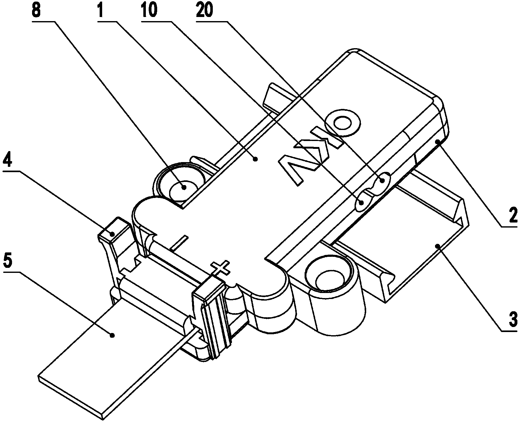
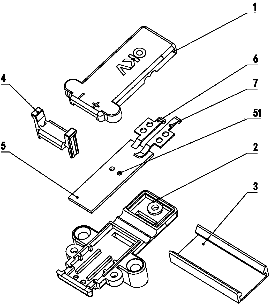
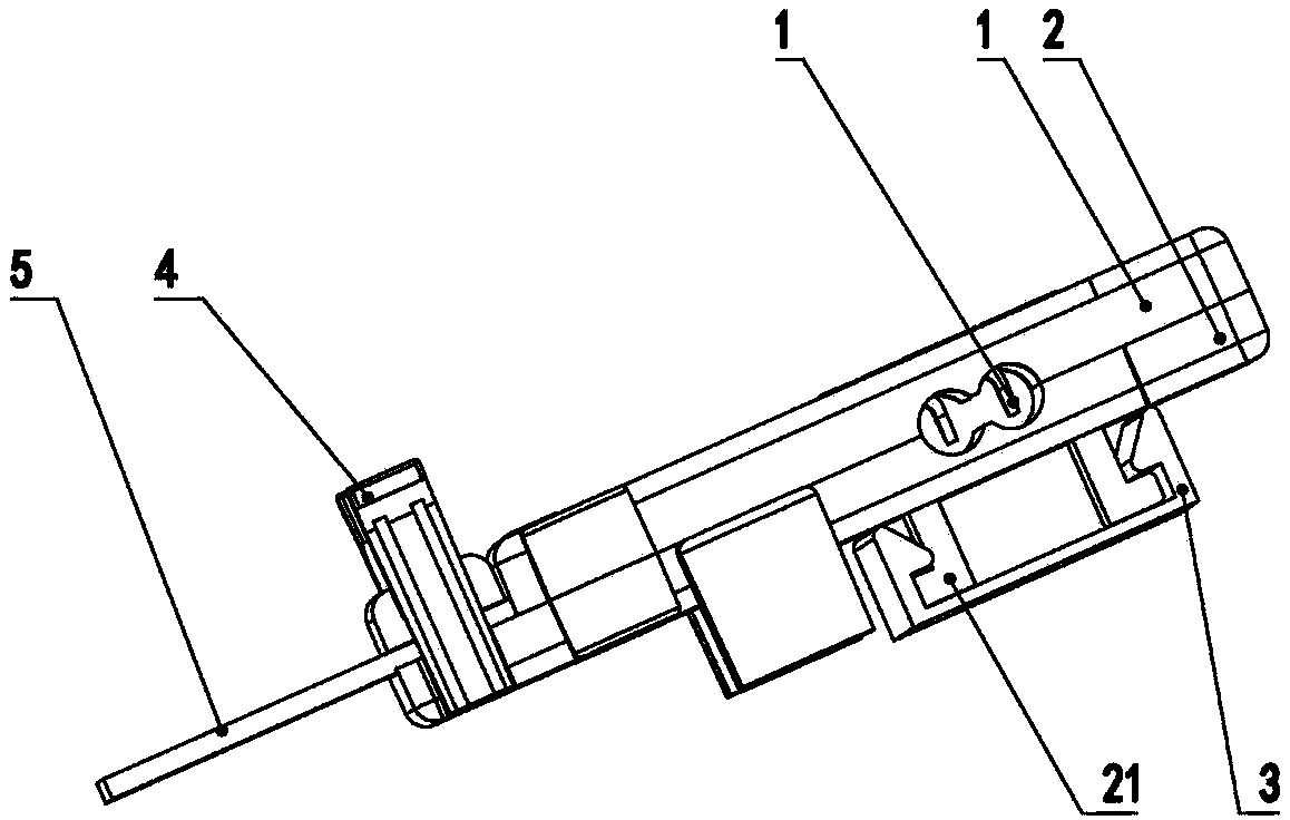
[0025] Figure 1 to Figure 8 The reference numerals in the figure are: guide rail type LED light bar socket 100; upper housing 1; lower housing 2; guide rail sliding feet 21; 4. Buckle pin 41; loose buckle wrench clip 42; fixing column 43; LED light bar 5; fixing hole 51; negative terminal 6; negative piercing protrusion 61; negative contact spring 62; positive terminal 7; positive The piercing protrusion 71 ; the positive electrode contact spring 72 ; the mounting screw hole 8 ; the wire 9 ; the negative electrode threading hole 10 ; the positive electrode threading hole 20 .

[0026] Such as Figure 1 to Figure 6 As shown, a rail-type LED light bar socket 100 includes an upper case 1, a lower case 2, a negative terminal 6 and a positive terminal 7, wherein a power supply is provided between the upper case 1 and the lower case 2. The negati...


PUM


Abstract

The invention provides a guide rail type LED light bar socket. The guide rail type LED light bar socket comprises an upper shell, a lower shell, a negative terminal and a positive terminal, wherein the upper shell is connected with the lower shell, a negative wire passing hole allowing a negative wire to pass through and a positive wire passing hole allowing a positive wire to pass through are formed between the upper shell and the lower shell, an installation cavity is defined between the upper shell and the lower shell, both the negative terminal and the positive terminal are arranged in the installation cavity, a negative impaling protrusion part is arranged at one end of the negative terminal, and a negative contact spring is arranged at the other end of the negative terminal. The invention further provides a guide rail type LED light bar extension socket connector. The guide rail type LED light bar socket and the guide rail type LED light bar extension socket connector have the advantages that the negative wire and the positive wire do not need to be cut into sections, operation such as welding is not needed, loss is small, consistent power supply on the head and on the tail can be achieved, luminance consistency is high, wiring management is convenient, installation is easy, insertion is convenient, and plug and play of an LED light bar is achieved.

Description

technical field [0001] The invention relates to a connecting device, in particular to a guide rail type LED light bar socket and a guide rail type LED light bar plug connector. Background technique [0002] LED light strips have been widely used at present, but when they are applied in large quantities, the power supply wiring is very inconvenient. Connect dozens of power plug wires. In order to connect these power plug wires, the main power wire is not a complete one, but cut into sections. The power plug wires are welded between each section, and the solder joints are insulated. Tape or heat-shrinkable tubes are wrapped, and the installation is complicated and labor-intensive. [0003] This method has a lot of wiring, messy, and troublesome wiring. Due to the large number of connectors, the loss on the wires is large, the power supply from the end to the end is inconsistent, and the brightness of the light is different. Contents of the invention [0004] In order to so...

Claims


Application Information

Patent Timeline
Patent Type & Authority Applications(China)
IPC IPC(8): H01R13/02H01R4/24H01R13/502H01R13/73
CPCH01R13/02H01R4/2404H01R13/502H01R13/73
Inventor 樊健平
Owner 樊健平
Learn More