Heat exchange tube spacing keeping structure

A heat exchange tube and spacing technology, applied in the field of heat exchange tube spacing maintenance structure, can solve the problems of maintaining the heat exchange tube spacing, unable to load and unload catalysts, etc., and achieve the effect of reasonable design and simple structure

Pending Publication Date: 2020-01-31
JIANGSU YONGDA CHEM MACHINERY
View PDF6 Cites 0 Cited by
  • Summary
  • Abstract
  • Description
  • Claims
  • Application Information

AI Technical Summary

Problems solved by technology

[0002] In the radial reactor, because the outer space of the heat exchange tube needs to be filled with catalyst, it is not possible to use a structure like a traditional baffle or support plate to maintain the distance between the heat exchange tubes, because such a structure cannot load and unload the catalyst

Method used


Image

  • Heat exchange tube spacing keeping structure
  • Heat exchange tube spacing keeping structure
  • Heat exchange tube spacing keeping structure

Examples


Embodiment Construction

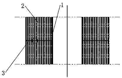
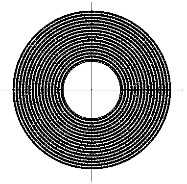
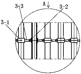
[0014] Such as Figure 1-4 As shown, a reactor tube bundle is used for a reactor tube bundle, and the reactor tube bundle includes an inner cylinder 1 and a plurality of heat exchange tubes 2, and a heat exchange tube distance maintenance structure 3 is used between the inner cylinder 1 and the plurality of heat exchange tubes 2 Fixed-distance connection; the heat exchange tube spacing maintenance structure 3 includes a number of ring sets 3-1, and all the ring sets 3-1 form several layers of concentric circles distributed concentrically; between two adjacent layers of ring sets 3-1, there are Positioning ring 3-2 and some positioning blocks 3-3, positioning ring 3-2 is set on all finger ring sleeves 3-1 of the inner layer, and is connected with all ring sleeves 3-2 of the inner layer by spot welding, positioning block 3- 3 Evenly distributed on the outer circumference of the positioning ring 3-2, spot welding connection with the positioning ring 3-2, and one-to-one correspond...


PUM


Abstract

The invention relates to a heat exchange tube spacing keeping structure which is used for a reactor tube bundle, and the reactor tube bundle comprises an inner cylinder and a plurality of heat exchange tubes; the heat exchange tube spacing keeping structure comprises a plurality of ring sleeves, and a plurality of layers of concentric circles which are concentrically distributed are defined by allthe ring sleeves; a positioning ring and a plurality of positioning blocks are arranged between every two adjacent layers of ring sleeves, the positioning rings sleeve all the ring sleeves on the inner layer and are fixedly connected with all the ring sleeves on the inner layer, and the positioning blocks are evenly distributed on the peripheries of the positioning rings, fixedly connected with the positioning rings and connected with all the ring sleeves on the outer layer in a one-to-one correspondence mode; all the rings on the innermost layer are arranged on the periphery of the inner cylinder in a sleeving mode and fixedly connected with the inner cylinder; and the heat exchange tubes are in one-to-one correspondence, penetrate through the ring sleeves and are fixedly connected withthe ring sleeves. Layered assembly of the heat exchange tubes can be realized; the distance between the heat exchange tubes can be fixed, a channel is reserved for a catalyst, and convenience is brought to catalyst loading and unloading.

Description

technical field [0001] The invention relates to a heat exchanger, in particular to a structure for maintaining the distance between heat exchange tubes. Background technique [0002] In the radial reactor, because the outer space of the heat exchange tube needs to be filled with catalyst, it is not possible to use a structure like a traditional baffle or support plate to maintain the distance between the heat exchange tubes, because such a structure cannot load and unload the catalyst. In addition, when assembling the tube bundle of the radial reactor, it is inconvenient to adopt the process of building the frame first and then threading the tubes, but it is necessary to assemble the heat exchange tubes layer by layer from the inside to the outside. Contents of the invention [0003] The invention proposes a space maintaining structure for a novel heat exchange tube bundle and an assembly process thereof. [0004] Technical scheme of the present invention: [0005] A hea...

Claims


Application Information

Patent Timeline
Patent Type & Authority Applications(China)
IPC IPC(8): B01J8/02B01J8/00
CPCB01J8/008B01J8/0285
Inventor 窦崇舟
Owner JIANGSU YONGDA CHEM MACHINERY
Why Eureka
Try Eureka