
Path planning device and path planning method for laser shot peening strengthening curved surface

A technology of laser shot peening and path planning, which is applied in the field of path planning of laser shot peening surface and path planning device of laser shot peening surface, can solve the problems of detection and elimination, large focusing error, large trajectory error, etc. Improve the utilization rate and ensure the effect of uniform consistency

Inactive Publication Date: 2017-11-07
GUANGDONG UNIV OF TECH
View PDF8 Cites 0 Cited by
  • Summary
  • Abstract
  • Description
  • Claims
  • Application Information

AI Technical Summary

Problems solved by technology

When using offline programming software for path planning, the accuracy of the model, the manufacturing accuracy of the workpiece, and the positioning accuracy of the workpiece are extremely high. The cumulative error of these factors makes the trajectory compiled by the offline programming software have a large error from the actual required trajectory, and there is no effective The means to detect and eliminate these errors; therefore, the manual focus method is the most commonly used path planning method. However, the conventional manual focus mainly relies on eye observation, and the focus error is also large, and it is difficult to ensure that the laser beam is perpendicular to the curved surface. Incidence point, need to invent a suitable method for path planning

Method used


Image

  • Path planning device and path planning method for laser shot peening strengthening curved surface
  • Path planning device and path planning method for laser shot peening strengthening curved surface
  • Path planning device and path planning method for laser shot peening strengthening curved surface

Examples


Embodiment Construction

[0024] Embodiments of the present invention are described in detail below.

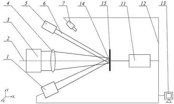
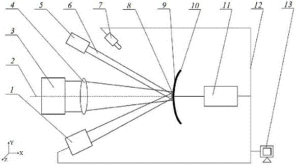
[0025] Such as figure 1 , figure 2As shown, the present invention is a path planning device for laser shot peening to strengthen curved surfaces, which includes a high-energy pulse laser 3, a positioning laser 5 symmetrically arranged on both sides with the centerline of the high-energy laser beam emitted by the high-energy pulse laser 3 as the working axis 2, and CCD display 1, a convex lens 4 positioned at the high-energy laser beam position on the front side of the high-energy pulse laser 3, a calibration block 15 with a calibration plane perpendicular to the working axis, a calibration reflective film 14 attached to the calibration plane, and a clamp to clamp the calibration block Or the workpiece and the manipulator 11 that can freely adjust its position and direction, the industrial computer 13 that is electrically connected to the CCD display 1 and the manipulator 11 through the data line, an...


PUM

PropertyMeasurementUnit
energyaaaaaaaaaa
diameteraaaaaaaaaa
diameteraaaaaaaaaa

Abstract

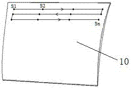
The invention discloses a path planning device of a laser shot blasting strengthened hook surface. The path planning device comprises a high energy pulse laser, a positioning laser, a CCD displayer, a correction block, a correction reflection film and a mechanical arm. The positioning laser and the CCD displayer are symmetrically arranged on the two sides, the correction block is provided with a correction plane, the correction reflection film is attached to the correction plane, the mechanical arm clamps and can freely adjust the correction block or a workpiece, and a visible laser beam is reflected to the CCD displayer. The invention further discloses a path planning method for the laser shot blasting strengthened hook surface. The parallel visible laser beam, the reflection film and the CCD displayer serve as positioning tools; the steps of distancing, positioning calibrating, tracing point positioning, coordinate recording, fitting of the coordinates into a trajectory path and the like are included; the device and method are adopted to conveniently and rapidly achieve running path planning of the hook surface in laser shot blasting strengthening, the method and device can be used for laser shot blasting strengthening of aircraft engine blades and steam turbine blades, the working position of the hook surface can be precisely located, the laser utilization rate is greatly improved, and power and density consistency in the strengthening process is ensured.

Description

technical field [0001] The invention relates to the technical field of laser processing, in particular to a path planning device for laser shot-peening strengthening curved surfaces. The invention also relates to a path planning method for laser shot-peening strengthening curved surfaces. Background technique [0002] Laser shot peening is a new material surface strengthening technology, which can obtain a high-amplitude residual compressive stress layer on the surface of metal parts, greatly improving the fatigue life of parts. Compared with conventional shot peening technology, its residual compressive stress layer is deeper . The principle of laser peening is to use pulsed laser (energy 1~100J, pulse width 10~30ns) to produce plasma explosion with the absorbing layer (aluminum foil or other materials) in a confined state (water film or glass), which can produce intensity up to several Gigapascal pressure, which spreads to the workpiece through the absorbing layer, can g...

Claims


Application Information

Patent Timeline
Patent Type & Authority Patents(China)
IPC IPC(8): C21D10/00
CPCC21D10/005
Inventor 刘新祥戴峰泽张永康黄志刚罗红平
Owner GUANGDONG UNIV OF TECH
Learn More