Eureka AIR delivers breakthrough ideas for toughest innovation challenges, trusted by R&D personnel around the world.

Spiral acoustic wave transmitting transducer containing vibration transmission rod

A technology of sound wave emission and vibration rod transmission, which is applied in the direction of the fluid using vibration, can solve the problems of complex drive mode of the transducer, increased navigation, poor phase directivity linearity, etc., and achieves the reduction of high-order vibration components, The effect of improving consistency and improving linearity

Active Publication Date: 2020-01-31
HARBIN ENG UNIV
View PDF11 Cites 0 Cited by
  • Summary
  • Abstract
  • Description
  • Claims
  • Application Information

AI Technical Summary

Problems solved by technology

Although these helical acoustic wave transducers can emit sound waves with phase directivity, the linearity of the phase directivity of these transducers is often not good, and there is a problem that the phase directivity varies with height, which adds additional to the navigation. The error of some transducers is too complicated to meet the needs of actual spiral acoustic navigation. How to realize the emission of spiral acoustic waves with high phase directivity, phase characteristics that do not change with height, and simple driving has become a concern of people. The problem

Method used


Image

  • Spiral acoustic wave transmitting transducer containing vibration transmission rod
  • Spiral acoustic wave transmitting transducer containing vibration transmission rod
  • Spiral acoustic wave transmitting transducer containing vibration transmission rod

Examples


Embodiment Construction

[0027] It should be noted that the embodiments of the present invention and the features in the embodiments can be combined with each other if there is no conflict.

[0028] Hereinafter, the present invention will be described in detail with reference to the drawings and in conjunction with the embodiments.

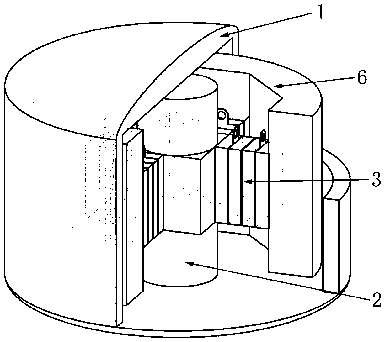
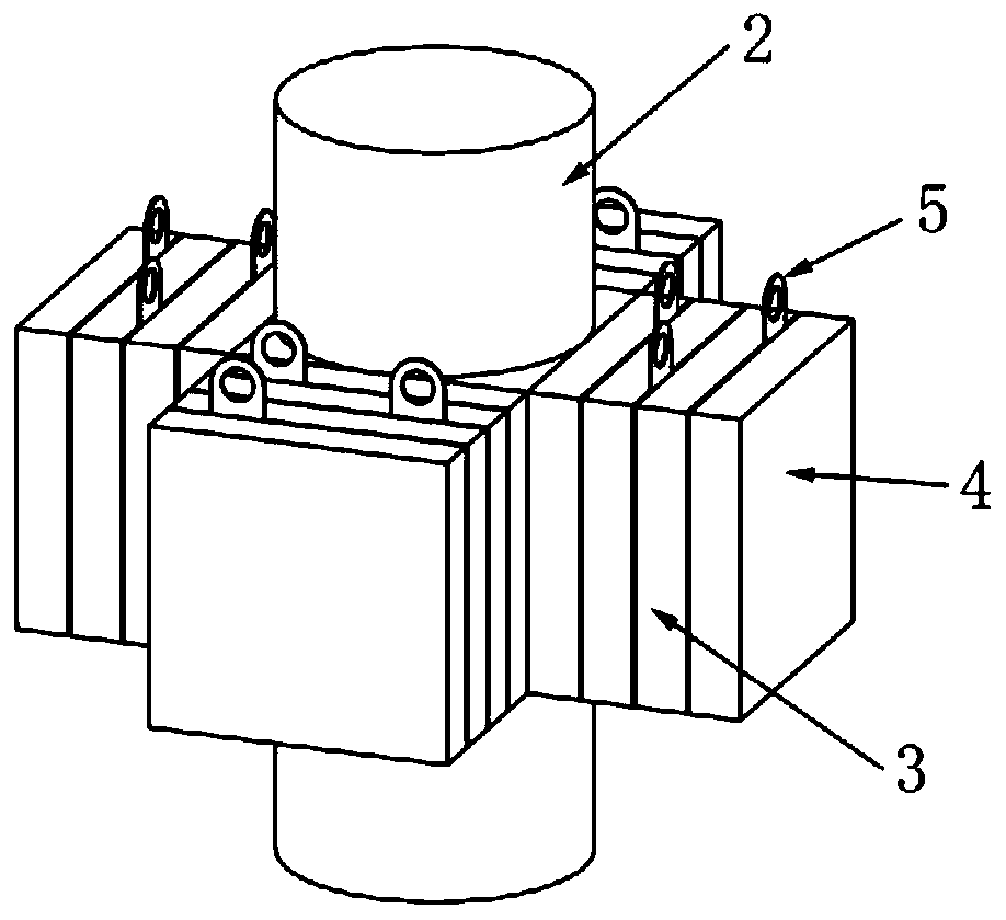
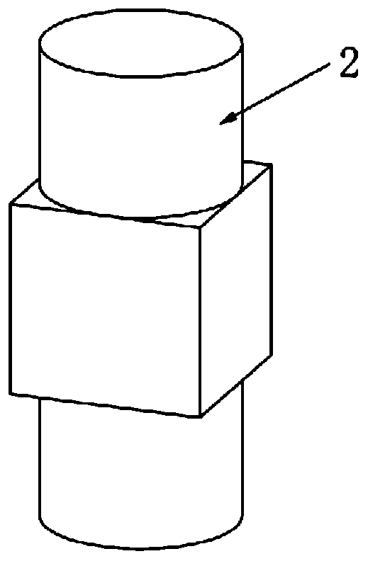
[0029] Such as Figure 1-Figure 4 As shown, a spiral acoustic wave transmitting transducer with a vibration transmission rod includes a vibration transmission rod 2, a piezoelectric ceramic stack 3 and a metal mass 6 arranged in a metal shell 1, and the vibration transmission rod 2 is provided At the center of the metal shell 1, and the upper and lower ends of the vibration transmission rod 2 are fixedly connected with the metal housing 1, several groups of piezoelectric ceramic stacks 3 are evenly distributed around the vibration transmission rod 2. The metal mass 6 It is sleeved on the periphery of the piezoelectric ceramic stack 3. Each piezoelectric ceramic stack 3 includ...


PUM


Abstract

The invention provides a spiral acoustic wave transmitting transducer containing a vibration transmission rod. The transducer comprises the vibration transmission rod arranged in a metal shell, piezoelectric ceramic stacks and metal mass blocks. The vibration transmission rod is arranged at the center of the metal shell, the upper end and the lower end of the vibration transmission rod are fixedlyconnected with the metal shell, a plurality of groups of piezoelectric ceramic stacks are uniformly distributed on the periphery of the vibration transmission rod, the metal mass blocks are arrangedat the peripheries of the piezoelectric ceramic stacks in a sleeving mode, each piezoelectric ceramic stack comprises a plurality of piezoelectric ceramic sheets and electrode sheets, the piezoelectric ceramic stacks are formed by staggered pressing of the piezoelectric ceramic sheets and the electrode sheets, and the two ends of each piezoelectric ceramic stack are provided with the correspondingpiezoelectric ceramic sheets. According to the spiral acoustic wave transmitting transducer containing the vibration transmission rod, the driving mode is simple, the phase directivity linearity is high, the phase characteristic does not change along with the height, the resonance frequency is relatively low, and the spiral acoustic wave transmitting transducer can be used for underwater acousticspiral acoustic wave navigation and underwater acoustic communication.

Description

Technical field [0001] The invention belongs to the field of underwater acoustic transducers, and in particular relates to a spiral acoustic wave emission transducer containing a vibration transmission rod. Background technique [0002] Sound waves are the only energy carrier known to humans that can be transmitted over long distances in sea water. Underwater navigation and positioning often use sound waves as the medium for carrying information. The underwater acoustic transducer, as a device that generates sound waves underwater, needs to be improved according to the needs of the times. [0003] In recent years, the rapid development of small-sized underwater vehicles has put forward the need for miniaturization and simplification of underwater navigation equipment. The American Benjamin Dzikowicz proposed a new underwater acoustic navigation technology based on the VOR technology in radio navigation. The phase directivity of the spiral sound wave realizes the navigation functi...

Claims


Application Information

Patent Timeline
Patent Type & Authority Applications(China)
IPC IPC(8): B06B1/06B06B3/00
CPCB06B1/0607B06B3/00B06B2201/74
Inventor 卢苇郭荣真蓝宇周天放
Owner HARBIN ENG UNIV
Why Eureka
Eureka Blog
Learn More