Punch structure and stamping method

A punch and stamping plate technology, applied in the field of stamping, can solve the problems of increasing the manufacturing process, reducing the flanging manufacturing efficiency, etc., and achieve the effect of saving the processing and manufacturing space and shortening the processing and manufacturing time.

Active Publication Date: 2020-01-31
宁波奥克斯厨电制造有限公司 +1
View PDF5 Cites 4 Cited by
  • Summary
  • Abstract
  • Description
  • Claims
  • Application Information

AI Technical Summary

Problems solved by technology

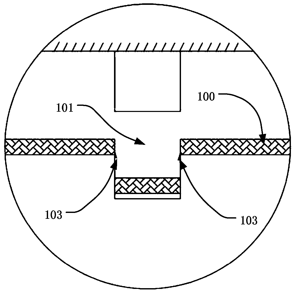
[0004] The purpose of the present invention is to solve the problem that burrs will be generated at the raised edges of the existing flanging of plate-like parts in the punching process, and the burrs need to be removed manually, which adds a new manufacturing process, thereby reducing the The problem of manufacturing efficiency of flanging

Method used


Image

  • Punch structure and stamping method
  • Punch structure and stamping method
  • Punch structure and stamping method

Examples


Embodiment Construction

[0056] In order to make the above objects, features and advantages of the present invention more comprehensible, specific embodiments of the present invention will be described in detail below in conjunction with the accompanying drawings.

[0057] In the description of the present invention, it should be understood that the orientation or positional relationship indicated by the terms "upper", "lower", "front" and "rear" are based on the orientation or positional relationship shown in the drawings, and are only for convenience The present invention is described and simplified descriptions do not indicate or imply that the device or element referred to must have a specific orientation, be constructed and operate in a specific orientation, and thus should not be construed as limiting the present invention.

[0058] The terms "first" and "second" are used for descriptive purposes only, and cannot be understood as indicating or implying relative importance or implicitly specifying...


PUM


Abstract

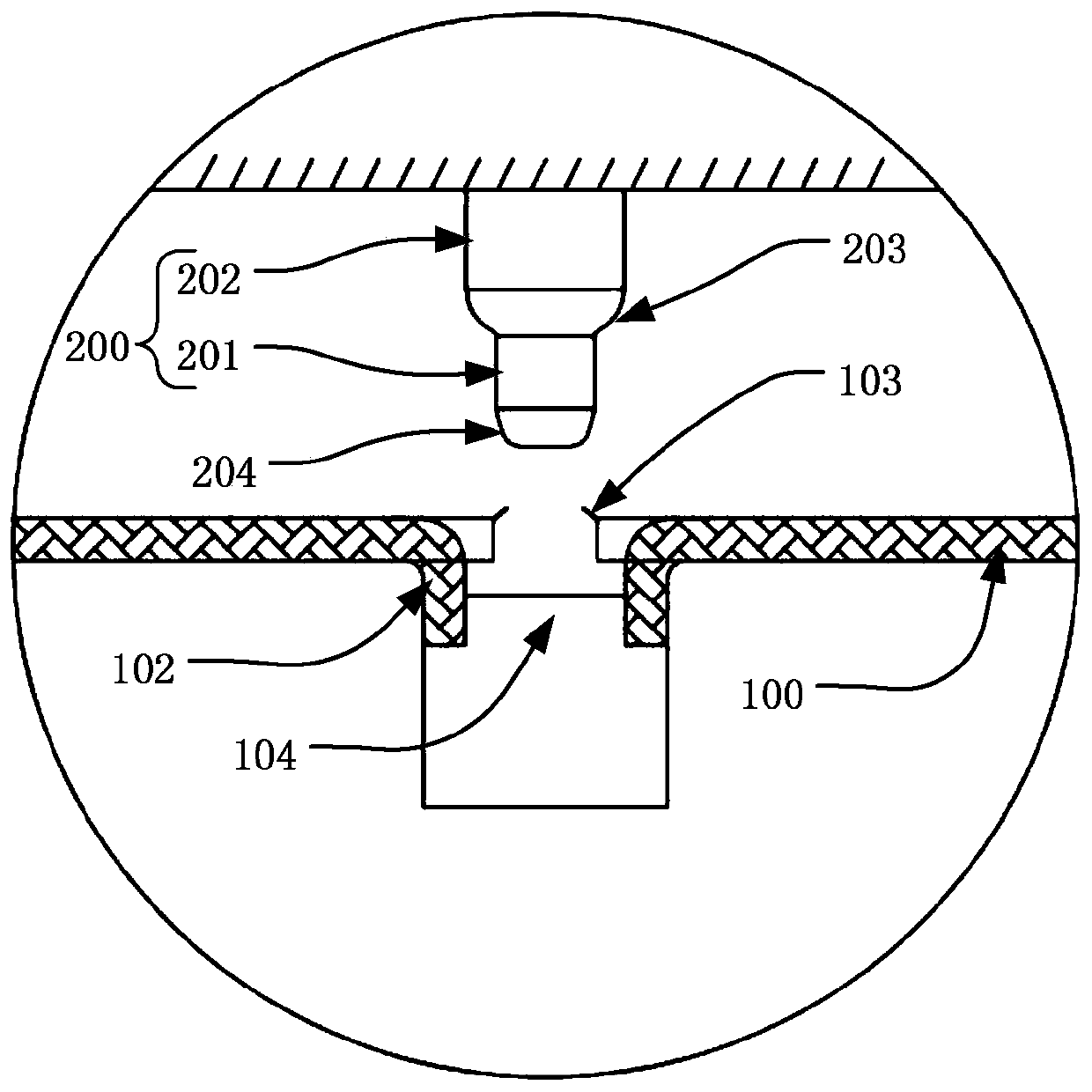
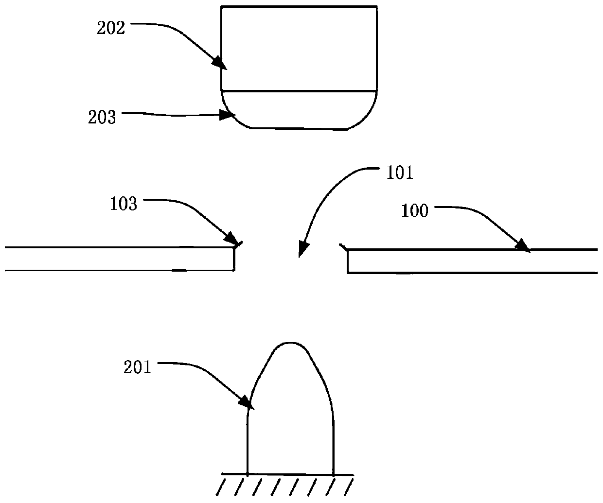
The invention provides a punch structure and a stamping method, and belongs to the technical field of stamping. The punch structure is used for stamping a plate-shaped piece, the plate-shaped piece isprovided with a first through hole, burrs are generated at the edge of the first through hole located on one side plate face of the plate-shaped piece, the punch structure comprises a second punch head part, the second punch head part is used for stamping and flanging from one side plate face of the plate-shaped piece to the other side plate face of the plate-shaped piece, the edge of the stamping end of the second punch head part is a second fillet transition, and the second fillet transition is used for removing the burrs. According to the punch structure, a mode of removing burrs manuallyis canceled, and the manufacturing process is saved, so that the manufacturing efficiency of flanging is improved.

Description

technical field [0001] The invention relates to the technical field of stamping, in particular to a punch structure and a stamping method. Background technique [0002] With the continuous advancement of technology, stamping technology has been widely used as the most efficient processing technology in mechanical processing, especially in the production process of home appliances, the shells, skeletons and other mechanisms of home appliances are generally prepared by stamping technology, and home appliances The shell, skeleton and other mechanisms of the product are usually made of plate-shaped parts through multiple stamping processes, and the plate-shaped parts usually need to be stamped out during the stamping process to facilitate the subsequent preparation process. [0003] However, during the stamping process of the flanging of the plate-shaped part, burrs will be generated at the raised edges thereof, and the burrs need to be removed manually, which adds a new manufac...

Claims


Application Information

Patent Timeline
Patent Type & Authority Applications(China)
IPC IPC(8): B21D37/10B21D19/08
CPCB21D19/005B21D19/08B21D37/10
Inventor 虞磊周红德张祖海
Owner 宁波奥克斯厨电制造有限公司
Why Eureka
Try Eureka