
Device capable of removing soldering tin of partial components on circuit board

A technology for circuit boards and components, applied in the field of solder removal devices, can solve the problems of time-consuming, labor-intensive, and easily damaged boards.

Inactive Publication Date: 2020-09-15
方德兰
View PDF0 Cites 2 Cited by
  • Summary
  • Abstract
  • Description
  • Claims
  • Application Information

AI Technical Summary

Problems solved by technology

[0002] With the continuous development of science and technology, the circuit board has become a kind of item that can be seen everywhere with solder removal devices for some components on the circuit board. For circuit boards, there are often soldering operations for its components. Currently, most Part of the soldering process on the circuit board is to remove the solder on the whole board, so that only the components are removed and the board is easily damaged. When only part of the components on the circuit board need to be soldered, most of them rely on Manual, which requires certain skills, and is time-consuming and laborious. A device for removing solder on some components on the circuit board described in the present invention can solve the above problems

Method used


Image

  • Device capable of removing soldering tin of partial components on circuit board
  • Device capable of removing soldering tin of partial components on circuit board
  • Device capable of removing soldering tin of partial components on circuit board

Examples


Embodiment Construction

[0015] Combine below Figure 1-Figure 5 The present invention is described in detail, and for convenience of description, the orientations mentioned below are now stipulated as follows: figure 1 The up, down, left, right, front and back directions of the projection relationship itself are the same.

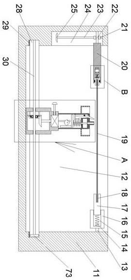
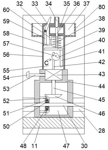
[0016]A device for removing solder on some components on a circuit board according to the present invention includes a housing 11, the housing 11 is provided with a working chamber 12 with an upward opening, and the lower wall of the working chamber 12 is moved with a The slider 44 is provided with a travel chamber 47 inside, the left and right walls of the travel chamber 47 are connected to slide and provided with a screw 30, and the side walls of the working chamber 12 are surrounded by a ring chamber 28 with an opening inward , the lower wall of the ring cavity 28 is provided with a ring rack 29, the right end of the screw 30 is fixedly connected with a steering wheel 73, and ...


PUM


Abstract

The invention discloses a device capable of removing soldering tin of partial components on a circuit board. The device capable of removing the soldering tin of the partial components on the circuit board comprises a shell; a working cavity with an upward opening is formed in the shell; a slide block is arranged on the lower wall of the working cavity in a mobile manner; an advancing cavity is formed in the slide block; a screw rod is slidingly arranged on the left and right wall of the advancing cavity in a communication manner; an annular cavity with an inward opening is formed in the side wall of the working cavity in a surrounded manner; an annular rack is arranged on the lower wall of the annular cavity; a steering wheel is fixedly connected to the right end of the screw rod; the lower end of the steering wheel is engaged with the annular rack; and a switching wheel is connected to the screw rod through threads. According to the device capable of removing the soldering tin of thepartial components on the circuit board, the soldering tin of the components on the circuit board can be selectively removed, and the components can be taken off; when the circuit board is put into the device, the circuit board can be well fixed by a clamping device so as to smoothly remove the soldering tin; during removing the soldering tin, the removing device can move in all directions so as to remove the soldering tin in each position; and moreover, during removing the soldering tin, the soldering tin is removed through vacuum suction so that the device is convenient and fast.

Description

technical field [0001] The invention relates to the field related to circuit boards, in particular to a device capable of removing solder from some components on the circuit board. Background technique [0002] With the continuous development of science and technology, the circuit board has become a kind of item that can be seen everywhere with solder removal devices for some components on the circuit board. For circuit boards, there are often soldering operations for its components. Currently, most Part of the soldering process on the circuit board is to remove the solder on the whole board, so that only the components are removed and the board is easily damaged. When only part of the components on the circuit board need to be soldered, most of them rely on Manual, which requires certain skills, and is time-consuming and labor-intensive. A device for removing solder from some components on the circuit board described in the present invention can solve the above-mentioned pr...

Claims


Application Information

Patent Timeline
Patent Type & Authority Applications(China)
IPC IPC(8): B23K1/018B23K3/08
CPCB23K1/018B23K3/087
Inventor 侯光喜
Owner 方德兰
Learn More