Blade clamping device and cutter with adjustable cutting angle including the device

A technology of clamping device and blade, applied in positioning device, clamping, manufacturing tools, etc., can solve the problems of inconvenient blade installation and complicated adjustment of cutting angle of the tool, and achieve the effect of compact structure, simple structure and easy adjustment.

Active Publication Date: 2021-06-18
HUAZHONG UNIV OF SCI & TECH
View PDF8 Cites 0 Cited by
  • Summary
  • Abstract
  • Description
  • Claims
  • Application Information

AI Technical Summary

Problems solved by technology

[0005] Aiming at the above defects or improvement needs of the prior art, the present invention provides a blade clamping device and a cutting angle-adjustable cutter including the device. The blade clamping device for cutting ceramic blades, stainless steel blades and other precision blades and the cutting angle adjustable tool including the device, thus solving the technical problems of inconvenient blade installation and complicated cutting angle adjustment methods in the prior art

Method used


Image

  • Blade clamping device and cutter with adjustable cutting angle including the device
  • Blade clamping device and cutter with adjustable cutting angle including the device
  • Blade clamping device and cutter with adjustable cutting angle including the device

Examples


Embodiment 1

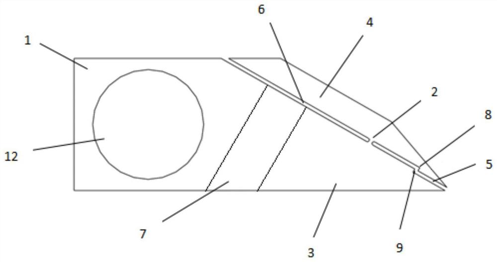
[0028] This embodiment provides a blade clamping device, such as figure 1 As shown, the fixture body 1 and fasteners are included. The fixture body 1 includes a fixed base 3 connected by a flexible hinge 2 and a pressing plate 4 that can rotate around the flexible hinge 2 , and the pressing plate 4 forms a lever structure together with the flexible hinge 2 . A blade mounting area 5 and a fastening area 6 are formed on both sides of the flexible hinge 2 , and the fixing base 3 of the fastening area 6 is provided with a fastener mounting hole 7 . One end of the fastener passes through the fastener installation hole 7 and abuts against the pressure plate 4 so that the blade is fixed in the blade installation area 5 . According to the principle of leverage, the pressing plate 4 clamps the blade in the blade installation area 5 to facilitate the installation of the blade. In this embodiment, the fasteners are screws. When working: the blade installation area 5 and the fastening ...

Embodiment 2

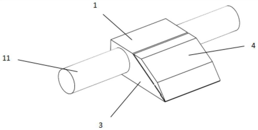
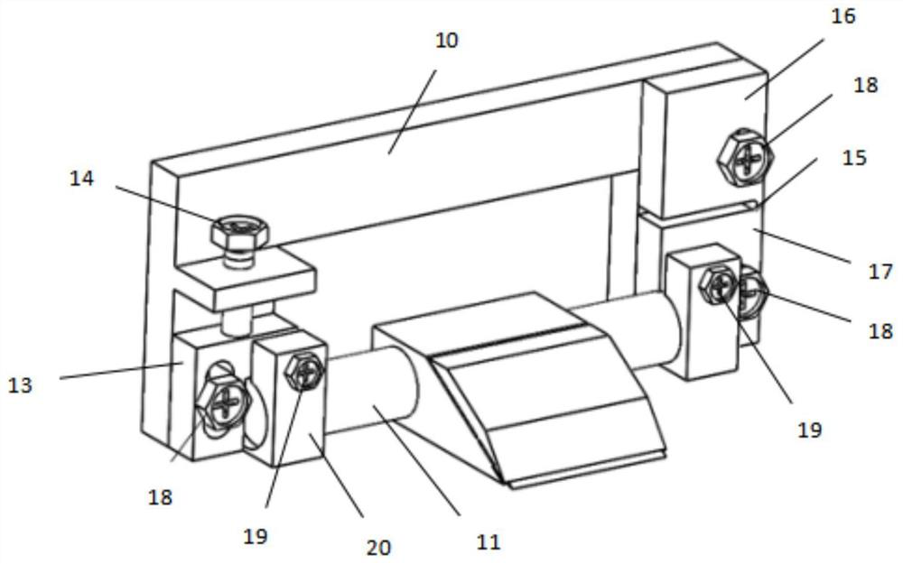
[0033] This embodiment provides a cutting tool with adjustable cutting angle, such as image 3 As shown, it includes the blade clamping device and the fixing frame 10 in the first embodiment, and the fixing frame 10 includes an angle adjustment assembly and a tool support rod 11 . Such as figure 1 , figure 2 As shown, the fixture body 1 in the blade clamping device is provided with a tool support rod installation hole 12, the blade clamping device is fixed on the tool support rod 11 through the tool support rod installation hole 12, and the tool support rod 11 is connected with the angle adjustment assembly . Through the above structure, the precise adjustment of the roll angle and pitch angle of the tool can be realized.

[0034] Such as image 3 As shown, the angle adjustment assembly includes a flexible connection plate, a movable plate 13 and a displacement adjustment assembly 14, the flexible connection plate includes a fixed plate one 16 and a fixed plate two 17 con...


PUM


Abstract

The invention discloses a blade clamping device and a tool with adjustable cutting angle including the device. The blade clamping device includes a clamp body and a fastener. The clamp body includes a fixed base connected by a flexible hinge and a flexible hinge that can be wound around. The rotating pressure plate forms a blade installation area and a fastening area on both sides of the flexible hinge. A fastener mounting hole is provided on the fixed base of the fastening area. After the fastener passes through the fastener mounting hole, one end of the fastener is against the pressure plate, so that The blade is fixed in the blade installation area, which solves the technical problem of inconvenient installation of the blade in the prior art. The tool with adjustable cutting angle includes a fixed frame and a blade clamping device. The fixed frame is equipped with an angle adjustment component and a tool support rod. The tool support rod is connected with the angle adjustment component, which solves the problem of complex cutting angle adjustment methods and low precision. technical issues.

Description

technical field [0001] The invention belongs to the field of clamps, and more specifically relates to a blade clamping device and a cutter with an adjustable cutting angle including the device. Background technique [0002] In the cutting of biological samples, the blade clamping device is a device for positioning and clamping the cutting blade. The existing method for clamping the blade is generally composed of two or more discrete rigid components, which are combined by screws and other parts. , to achieve the clamping of the blade. [0003] Using the above-mentioned clamping method, one is inconvenient to install; the other is that the clamping force of the blade is uncontrollable. For precision thin blades with poor rigidity or brittleness, it is easy to form point contact or line contact constraints, which will generate greater pressure on the blade. / pressure, easy to damage the blade; at the same time, the pressure / pressure is unevenly distributed on the blade, causi...

Claims


Application Information

Patent Timeline
Patent Type & Authority Patents(China)
IPC IPC(8): B23Q3/04
CPCB23Q3/04
Inventor 袁菁骆清铭邓磊陈键伟龚辉
Owner HUAZHONG UNIV OF SCI & TECH
Why Eureka
Try Eureka