Impact-resistant vacuum glass

A technology of vacuum glass and impact resistance, which is applied in the direction of climate change adaptation, window/door improvement, etc. It can solve problems such as seal damage, vacuum glass damage, glass plate fragmentation, etc., and achieve the effect of improving impact resistance

Pending Publication Date: 2020-01-31
LUOYANG LANDGLASS TECH CO LTD
View PDF0 Cites 2 Cited by
  • Summary
  • Abstract
  • Description
  • Claims
  • Application Information

AI Technical Summary

Problems solved by technology

Due to the following structure of the vacuum glass, the vacuum glass often cannot meet the requirements of the standard: (1) The inner cavity of the vacuum glass is provided with a hard support. When the falling ball is impacted, it is easy to form a Stress concentration, which causes the glass plate to shatter
(2) When the sealing material of vacuum glass is low-melting glass powder, because the low-melting glass powder is a brittle material, it will cause damage to the seal after being impacted, thus making the vacuum glass invalid
In addition, when low glass powder is used for sealing, since the sealing temperature is around 450°C, the glass substrate will be greatly de-tempered, and the falling ball impact test will cause greater damage to the vacuum glass

Method used


Image

  • Impact-resistant vacuum glass
  • Impact-resistant vacuum glass
  • Impact-resistant vacuum glass

Examples


Embodiment 1

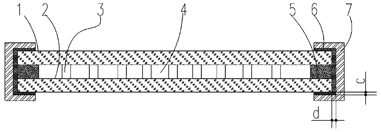
[0049] An impact-resistant vacuum glass, including a vacuum glass body. In this embodiment, the vacuum glass body includes a first glass substrate 1 and a second glass substrate 2, and the first glass substrate 1 and the second glass substrate 2 are arranged oppositely, and a metal sealing material 5 is consolidated on the inner side of the peripheral plate surface of the first glass substrate 1 and the second glass substrate 2, and a vacuum chamber 4 is formed between the two glass substrates and the metal sealing material, surrounded by Multiple supports 3 are arranged between the two glass substrates of the vacuum chamber 4 .

[0050] In this embodiment, a buffer material 6 is provided on the end face side of the periphery of the vacuum glass body and on the outer sides of the two boards of the periphery of the vacuum glass body, and a dynamic stress offset frame 7 is wrapped and fixed on the outer side of the buffer material. figure 1 It can be seen that, in this embodime...

Embodiment 2

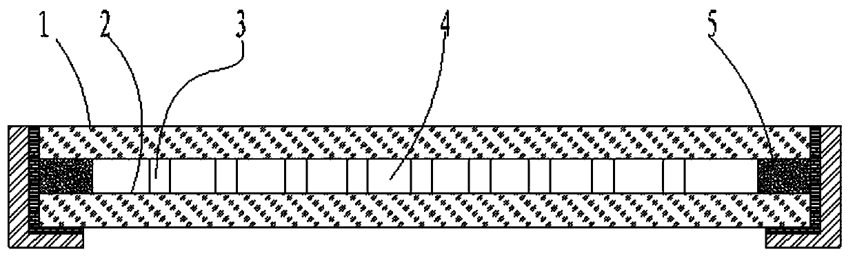
[0068] Compared with the first embodiment, the difference between this embodiment and the first embodiment is that a buffer material 6 is arranged on the end face side of the periphery of the vacuum glass body and a plate surface outside the periphery of the vacuum glass body, and a dynamic stress offset frame 7 is wrapped and fixed on the outside of the buffer material. figure 2 It can be seen that, in this embodiment, the cross-sectional shape of the dynamic stress offset frame 7 is L-shaped. The rest are all the same as in Example 1.

Embodiment 3

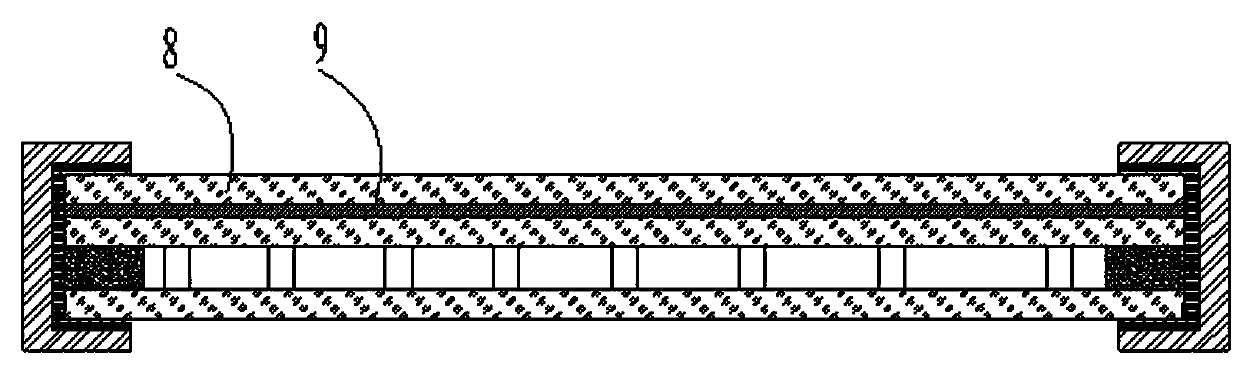
[0070] Compared with the first embodiment, the difference between this embodiment and the first embodiment is that the vacuum glass body includes a first glass substrate 1 and a second glass substrate 2 that surround the vacuum cavity, and a glass substrate that is connected to the first glass substrate 1 or the second The third glass substrate 8 where the two glass substrates 2 are oppositely arranged, the buffer material 6 is arranged on the outer side of the third glass substrate 8 in the vacuum glass body and in the first and second glass substrates away from the third glass substrate 8 The outer side of the glass substrate, such as image 3 shown.

[0071] In this embodiment, an organic polymer interlayer film 9 is arranged between the third glass substrate 8 and the first glass substrate 1 or the second glass substrate 2, and the organic polymer interlayer film 9 can be PVB, SGP, EVA, laminated glass glue, etc., the organic polymer interlayer film can be set in one or m...


PUM

PropertyMeasurementUnit
thicknessaaaaaaaaaa
elastic modulusaaaaaaaaaa
tensile strengthaaaaaaaaaa

Abstract

The invention discloses impact-resistant vacuum glass comprising a vacuum glass body, wherein the vacuum glass body comprises a first glass substrate, a second glass substrate, a sealing material anda support, wherein an upper glass substrate and a lower glass substrate are oppositely arranged; the sealing material is arranged at the edge position between the upper glass substrate and the lower glass piece; a vacuum cavity is defined by the upper glass substrate, the lower glass substrate and the sealing material together. The support is arranged in the vacuum cavity, a buffer material is arranged on the end face side of the periphery of the vacuum glass body and the outer side of at least one plate face of the periphery of the vacuum glass body, a dynamic stress counteracting frame is arranged on the outer side of the buffer material, and the dynamic stress counteracting frame can apply size-adjustable preloading force to the edge of the vacuum glass. The impact resistance of the vacuum glass can be remarkably improved, and the vacuum glass has great application and popularization prospects.

Description

technical field [0001] The invention relates to the technical field of vacuum glass manufacturing, in particular to a shock-resistant vacuum glass. Background technique [0002] Vacuum glass is a new type of energy-saving and environmentally friendly glass. It is widely loved by consumers due to its high heat insulation and sound insulation performance. Vacuum glass usually includes two independent glass substrates, forming a low-pressure space between the two glass substrates. (i.e. vacuum chamber), two glass substrates are connected by edge sealing, a support is set in the vacuum chamber between the two glass substrates, and the support is used to withstand the pressure difference between the external atmospheric pressure and the vacuum chamber , thereby preventing damage to the glass substrate. [0003] Due to the special structure of the vacuum glass and the low-pressure environment in the vacuum chamber, the outer surface of the vacuum glass bears a large tensile stres...

Claims


Application Information

Patent Timeline
Patent Type & Authority Applications(China)
IPC IPC(8): C03C27/06C03C27/08C03C27/10
CPCC03C27/06C03C27/08C03C27/10Y02B80/22Y02A30/249
Inventor 赵雁李彦兵张红霞李素真
Owner LUOYANG LANDGLASS TECH CO LTD
Why Eureka
Try Eureka