Moistening device of fabric pre-shrinking equipment

A wet supply device and wet supply technology are applied in the direction of processing textile material equipment configuration, textile material processing, and textile material drum processing. It can solve the problems of affecting the quality of pre-shrinking processing, single steam outlet, and uneven wet supply. Achieve the effect of improving steam utilization rate, prolonging service life, and small contact area

Inactive Publication Date: 2020-01-31
湖州菠萝蜜服饰有限公司
View PDF7 Cites 3 Cited by
  • Summary
  • Abstract
  • Description
  • Claims
  • Application Information

AI Technical Summary

Problems solved by technology

[0002] The pre-shrinking device for apparel fabrics is an indispensable finishing device in the production and processing of apparel. The pre-shrinking treatment of the fabric can stabilize the shrinkage rate and further improve the quality and dimensional stability of the fabric. The existing pre-shrinking devices mostly use Dry separate pre-shrinking device, before the pre-shrinking treatment, the wet supply device performs wet treatment. According to the processing requirements of different fabrics, the wet supply is controlled between 10% and 20%, and steam is generally used for wet treatment. To wet the fabric, arrange the steam outlet pipe in the humidifying device to wet the fabric evenly. At present, the humidifying device generally inputs the fabric from one end of the device and outputs from the other end. The steam outlet is located at the upper and lower ends of the fabric, and the fabric is in the humidifying device. The conveying formation is short and the steam outlet is single, which easily leads to uneven and insufficient moisture supply, which affects the quality of subsequent pre-shrinking processing

Method used


Image

  • Moistening device of fabric pre-shrinking equipment
  • Moistening device of fabric pre-shrinking equipment
  • Moistening device of fabric pre-shrinking equipment

Examples


Embodiment

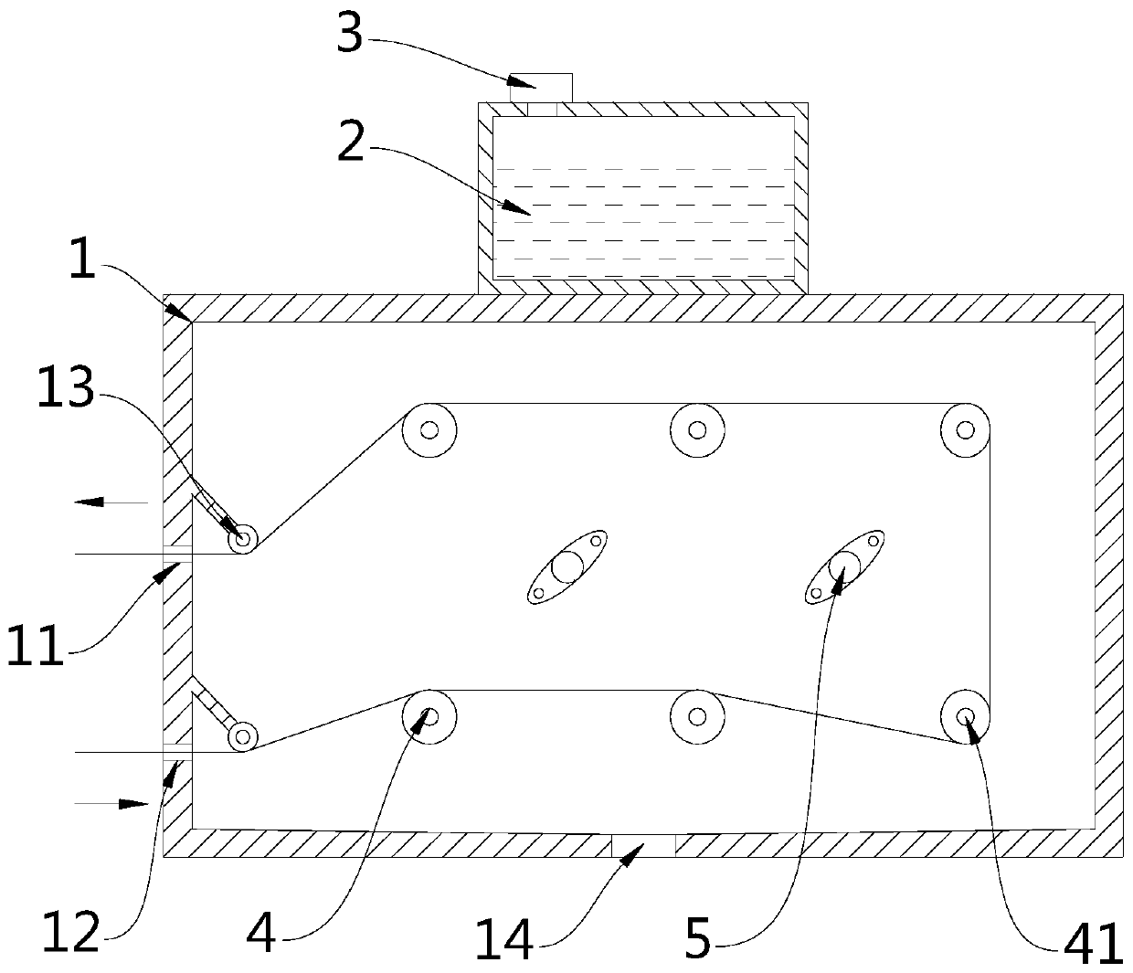
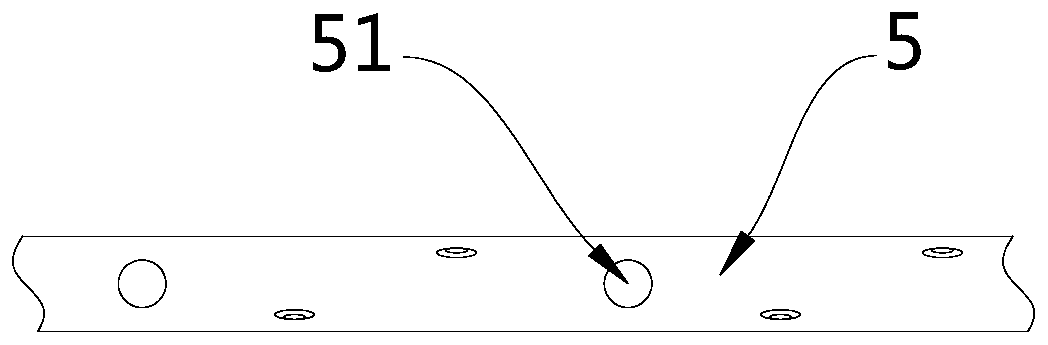
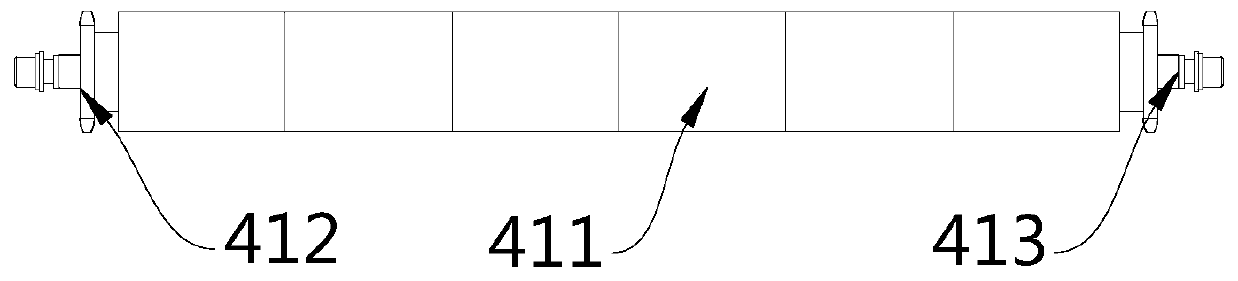
[0028] Embodiment: a kind of moisture supply device of fabric pre-shrinking equipment, the structure is as follows Figure 1 to Figure 8 As shown, it includes a humidity supply box 1, the humidity supply box 1 is connected with a water storage tank 2, and the water storage tank 2 is connected with a steam generator 3, and the upper and lower sides of the same side of the humidity supply box 1 are respectively provided with cloth outlets. 11 and cloth inlet 12, fabrics are realized on the same side and come in and out, and cloth outlet 11 and cloth inlet 12 are provided with guide roller 13 on the inside corresponding to the humidifying box body 1, and the upper and lower two sides are arranged inside the humidifying box body 1. Rows of driving rollers 4, several steam outlet pipes 5 are arranged between the two rows of driving rollers 4, the two end driving rollers 4 far away from the guide rollers 13 in the two rows of driving rollers 4 are corner driving rollers 41, the two r...


PUM


Abstract

The invention discloses a moistening device of fabric pre-shrinking equipment. The moistening device comprises a moistening box body, wherein a water storage tank is connected to the moistening box body; a steam generator is connected to the water storage tank; a cloth outlet and a cloth inlet are respectively formed in the upper and lower parts of the same side of the moistening box body; guide rollers are respectively arranged on the inner side of the moistening box body corresponding to the cloth outlet and the cloth inlet; an upper row and a lower row of transmission rollers are arranged inside the moistening box body; a plurality of steam outlet pipes are arranged between the two rows of transmission rollers; two end transmission rollers far away from the guide rollers in the two rowsof transmission rollers are corner transmission rollers; and the roller body sections of the corner transmission rollers are oval. The device has the advantages that the input fabric has a longer stroke in the device, the fabric can be given more sufficient moisture supply, and the relative positions of the transmission rollers and the steam outlet pipes are arranged, so that the fabric can be given uniform moisture supply.

Description

technical field [0001] The invention relates to a moisture supply device for fabric, in particular to a moisture supply device for fabric pre-shrinking equipment. Background technique [0002] The pre-shrinking device for apparel fabrics is an indispensable finishing device in the production and processing of apparel. The pre-shrinking treatment of the fabric can stabilize the shrinkage rate and further improve the quality and dimensional stability of the fabric. The existing pre-shrinking devices mostly use Dry separate pre-shrinking device, before the pre-shrinking treatment, the wet supply device performs wet treatment. According to the processing requirements of different fabrics, the wet supply is controlled between 10% and 20%, and steam is generally used for wet treatment. To wet the fabric, arrange the steam outlet pipe in the humidifying device to wet the fabric evenly. At present, the humidifying device generally inputs the fabric from one end of the device and out...

Claims


Application Information

Patent Timeline
IPC IPC(8): D06B3/12D06B23/02D06B23/04D06B23/20
CPCD06B3/12D06B23/023D06B23/04D06B23/205
Inventor 徐斌
Owner 湖州菠萝蜜服饰有限公司
Why Eureka
Try Eureka