
Fourdrinier equipped with top former

A technology for a Fourdrinier paper machine and a former, which is applied in the field of papermaking, can solve problems such as poor paper quality, and achieve the effects of improving paper evenness, reducing fiber flocs, and improving paper quality.

Pending Publication Date: 2020-01-31
宁夏星河新材料科技有限公司
View PDF0 Cites 0 Cited by
  • Summary
  • Abstract
  • Description
  • Claims
  • Application Information

AI Technical Summary

Problems solved by technology

[0003] The purpose of the present invention is to solve the shortcomings of poor paper quality in the prior art, and propose a fourdrinier paper machine equipped with a top wire former

Method used


Image

  • Fourdrinier equipped with top former
  • Fourdrinier equipped with top former
  • Fourdrinier equipped with top former

Examples


Embodiment 1

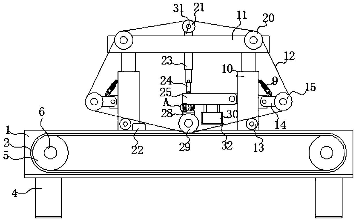
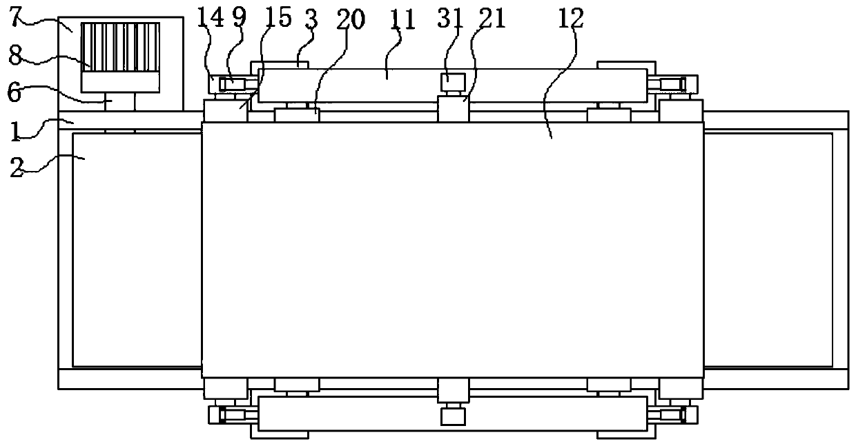
[0022] refer to Figure 1-2 , a fourdrinier paper machine equipped with a top wire former, comprising a transfer bin 1, both sides of the inner wall of the transfer bin 1 are movably connected with transfer shafts 5, one of which is connected by a rotating mechanism, and the transfer shaft 5 is fitted with The lower net 2 is installed, and the bottom plate 3 is fixed around the transfer chamber 1. The hydraulic rod 10 is fixed on the bottom plate 3, and the upper plate 11 is fixed above the hydraulic rods 10 on both sides. Both sides of the two upper plates 11 rotate. There is a return roller 20 connected, and a forming roller 13 is connected to the bottom between the two hydraulic rods 10, and a suction vacuum box 22 is installed on the transfer chamber 1 on one side of one of the forming rollers 13, and the lower side of the hydraulic rod 10 is rotatably connected. There are side plates 14, and a mesh guide roller 15 is rotatably connected between the two side plates 14, and...

Embodiment 2

[0025] refer to Figure 1-2 , as another preferred embodiment of the present invention, the difference from Embodiment 1 is that the rotating mechanism includes a support plate 7, the support plate 7 is fixed on one side of the transfer bin 1, and a motor 8 is installed on the support plate 7, and the motor 8- The side is connected with one end of the rotating shaft 6, and the other end of the rotating shaft 6 passes through the transmission bin 1 and is connected with the transmission rotating shaft 5. The lower net 2 can be driven to move by the rotating mechanism, and the wet paper on the lower net 2 can be driven to move.

Embodiment 3

[0027] refer to Figure 1-2 , as another preferred embodiment of the present invention, the difference from Embodiment 1 is that an upper connecting plate 31 is fixed in the middle of the top of the upper plate 11, and a school screen roller 21 is rotatably connected between the upper connection plates 31, and the school screen roller The top of 21 is in contact with the top net 12, and the top of the top net 12 can be better supported by the school screen roller 21.


PUM


Abstract

The invention relates to the technical field of papermaking, in particular to a fourdrinier equipped with a top former. The fourdrinier comprises a transfer bin, wherein transferring rotation shafts are movably connected to two sides of the inner wall of the transfer bin, and one of the transferring rotation shafts is connected through a rotating mechanism; a lower wire is mounted on the transferring rotation shafts in a matched manner; bottom plates are fixed to the periphery of the transferring bin; hydraulic rods are fixed to the bottom plates; upper plates are fixedly installed above the hydraulic rods located at two sides; return rollers are rotatably connected to the two sides of space located between the two upper plates; forming rollers are rotatably connected to the lower portionsof the two hydraulic rods and located between the two hydraulic rods; and a pipetting vacuum box is installed on the portion, on one side of one forming roller, of the conveying bin. According to thefourdrinier, the lower wire can move under the driving of the rotating mechanism, so wet paper sheets on the lower wire can be driven to move; and the wet paper sheets pass through the space betweena top wire and a lower wire table in the forming process, so the upper face and the lower face of a paper web are dewatered.

Description

technical field [0001] The invention relates to the technical field of papermaking, in particular to a fourdrinier paper machine equipped with a top wire former. Background technique [0002] The existing domestic medium and low-speed fourdrinier paper machines mostly use the shaking of the screen table or the installation of finishing rollers (also called watermark rollers) to improve the evenness of the paper sheets, but the improvement range is limited, and these methods can only be used in On a low-speed paper machine, once the speed of the paper machine exceeds a certain range, the vibration of the screen table and the use of finishing rollers will be limited. The shaking device cannot be used because the amplitude and vibration times cannot adapt to high speeds, and the finishing rollers must also be increased. Large diameter and additional transmission also have very strict requirements for manufacturing accuracy and installation position. Improper use may damage the ...

Claims


Application Information

Patent Timeline
Patent Type & Authority Applications(China)
IPC IPC(8): D21F3/02
CPCD21F3/02
Inventor 郭旭斌张金霞石龙马玉春贾燕周斌
Owner 宁夏星河新材料科技有限公司
Learn More