
Shell and electronic equipment

A shell and base technology, applied in the direction of electrical equipment shell/cabinet/drawer, electrical components, chassis/cabinet/drawer parts, etc., can solve problems such as difficulty in satisfying users

Active Publication Date: 2020-01-31
GUANGDONG OPPO MOBILE TELECOMM CORP LTD
View PDF14 Cites 12 Cited by
  • Summary
  • Abstract
  • Description
  • Claims
  • Application Information

AI Technical Summary

Problems solved by technology

The current casing usually forms a casing with a certain color, texture, and metallic luster by screen-printing color ink on the substrate, transferring UV texture, coating, or pasting an appearance film, etc. Once the above-mentioned casing is prepared , its appearance color, pattern, etc. are fixed and immutable, so it is difficult to meet the various needs of users
[0003] However, the current housing and electronic equipment still need to be improved.

Method used


Image

  • Shell and electronic equipment
  • Shell and electronic equipment
  • Shell and electronic equipment

Examples


Embodiment Construction

[0021] Examples of the application are described in detail below, which examples are illustrated in the accompanying drawings. The examples described below by referring to the accompanying drawings are exemplary and are intended to explain the present application and should not be construed as limiting the present application.

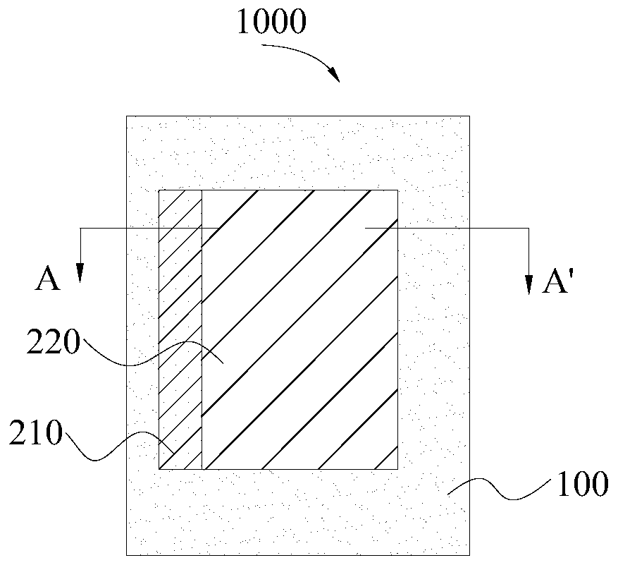
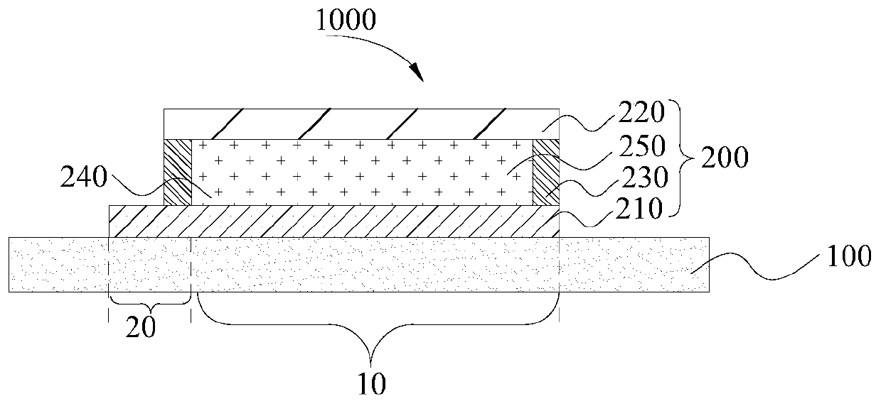
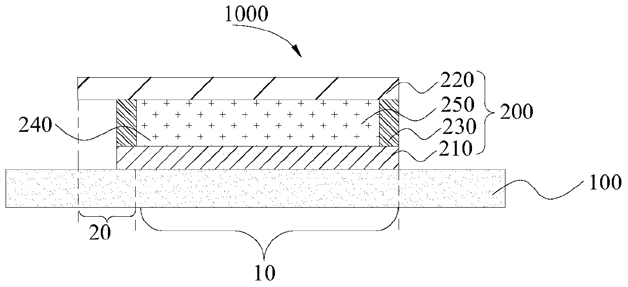
[0022] In one aspect of the present application, the present application provides a casing. According to some examples of this application, refer to figure 1 as well as figure 2 ( figure 2 for along figure 1 The schematic diagram of the cross-sectional structure in the AA' direction in the center), the housing 1000 includes: a housing base 100 and a dye liquid crystal color-changing device 200, wherein the dye liquid crystal color-changing device 200 is arranged on at least a part of the surface of the housing base 100, and the dye liquid crystal color-changing device 200 includes a first transparent conductive layer 210, a second transparent con...


PUM

PropertyMeasurementUnit
widthaaaaaaaaaa
electrical resistanceaaaaaaaaaa
thicknessaaaaaaaaaa

Abstract

The invention discloses a shell and electronic equipment. The shell comprises a shell base body and a dye liquid crystal color changing device; the dye liquid crystal color changing device is arrangedon at least one part of the surface of the shell base body; the dye liquid crystal color changing device comprises a first transparent conductive layer, a second transparent conductive layer, an frame sealing adhesive and a dye liquid crystal layer; the first transparent conductive layer and the second transparent conductive layer are oppositely arranged; the frame sealing adhesive is arranged between the first transparent conductive layer and the second transparent conductive layer; an accommodating space is defined between the first transparent conductive layer and the second transparent conductive layer; the dye liquid crystal layer is arranged in the accommodating space; the dye liquid crystal color changing device is provided with a first terminal electrically connected with the first transparent conductive layer and a second terminal electrically connected with the second transparent conductive layer, wherein the first terminal is located on one side, far away from the accommodating space, of the frame sealing adhesive, and the first terminal and the second terminal are located on the same side of the dye liquid crystal layer. Therefore, the shell has the advantages of richcolor effects, color changing effects, good appearance and high product expressive force.

Description

technical field [0001] The present application relates to the field of electronic equipment, in particular, to casings and electronic equipment. Background technique [0002] With the continuous development of preparation technology in the field of electronic equipment, housing materials for electronic equipment are also abundant. With the improvement of consumption level, consumers not only pursue the diversification of functions of electronic products, but also have higher and higher requirements for their appearance and texture. The current casing usually forms a casing with a certain color, texture, and metallic luster by screen-printing color ink on the substrate, transferring UV texture, coating, or pasting an appearance film, etc. Once the above-mentioned casing is prepared , its appearance color, pattern, etc. are fixed and immutable, so it is difficult to meet the various needs of users. [0003] However, the current housing and electronic equipment still need to ...

Claims


Application Information

Patent Timeline
Patent Type & Authority Applications(China)
IPC IPC(8): H05K5/00H05K5/02
CPCH05K5/0017H05K5/0069H05K5/0247
Inventor 杨鑫
Owner GUANGDONG OPPO MOBILE TELECOMM CORP LTD
Learn More