
Method and device for cleaning ionization electrodes

An ionization electrode, electrode technology, applied in the field of cleaning ion ionization electrodes

Active Publication Date: 2021-11-23
塔迪兰消费技术产品有限公司
View PDF11 Cites 0 Cited by
  • Summary
  • Abstract
  • Description
  • Claims
  • Application Information

AI Technical Summary

Problems solved by technology

[0011] A problematic issue common to all known devices is the removal of debris from the spot cleaning point

Method used


Image

  • Method and device for cleaning ionization electrodes
  • Method and device for cleaning ionization electrodes
  • Method and device for cleaning ionization electrodes

Examples


Embodiment Construction

[0039] In the following description of some embodiments, similar components appearing in multiple drawings or sharing similar functions will refer to the same reference symbols.

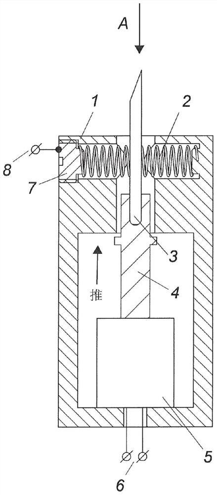
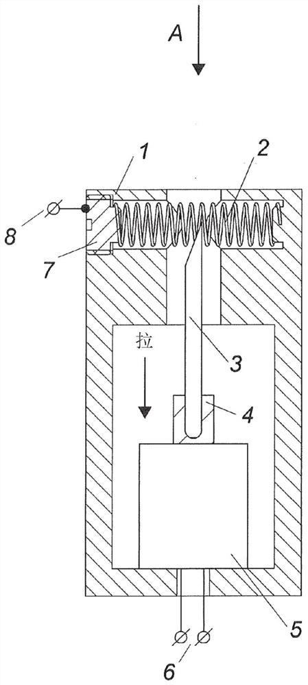
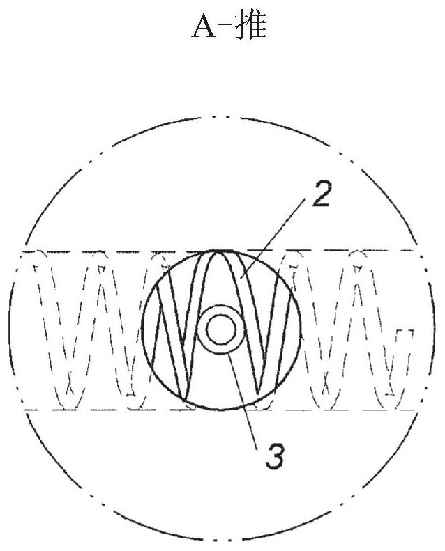
[0040] figure 1 is a schematic diagram of an electrode cleaning device set in "ionization" mode according to a first embodiment of the present invention. The device comprises the following elements: a body 1, a coil spring 2 formed of an electrically conductive material, an ionizing electrode 3 adapted to move axially in a chamber of said body, a coil spring of an insulating material Plunger 4 forming part of an actuator 5 , a power supply terminal 6 of said actuator 5 , a contact element 7 formed of an electrically conductive material and a high voltage supply terminal 8 . The contact element 7 supports an end point of the coil spring 2 and allows a high voltage to be supplied thereto via the supply terminal 8 . In a "push" or "ionization" mode of operation, the actuator 5 is adapted to push the ...


PUM


Abstract

An apparatus for cleaning an ionizing electrode comprising: a coil spring fixedly mounted at opposite ends; and an ionizing electrode operable by an actuator plunger along a path relative to an axis of the coil spring reciprocating movement, the route extends from an outer periphery of the spring to an inner periphery thereof, so that during each reciprocating movement, a tip of the electrode penetrates an entire cross-section of the coil spring to provide The ends intersect the adjacent coils so that each coil is able to collect dust and other waste deposits from the electrodes.

Description

technical field [0001] The present invention relates to a method and device for cleaning ionization electrodes and can be applied in household appliances as well as in industry. Background technique [0002] Solutions are known for cleaning electrodes from dust, wherein the cleaning device travels during cleaning relative to a stationary ionizing electrode or set of electrodes (see, for example, WIPO Publication Nos. WO 2012 / 176099 and US Patent No. 8,106,367). [0003] The cleaning device disclosed in the World Intellectual Property Organization Publication No. WO / 2012 / 176099 is formed as a layer of porous fibrous material or a layer of finely dispersed balls arranged between two multi-nested grids, the grid's The size is greater than the diameter of the ionization electrode. At the same time, the whole device is designed as a non-standard solenoid, wherein the permanent magnet and the cleaning device base move relative to the fixed coil. [0004] A disadvantage of this ...

Claims


Application Information

Patent Timeline
Patent Type & Authority Patents(China)
IPC IPC(8): B03C3/74H01T23/00
CPCB03C3/41B03C3/743B03C3/746B03C2201/06H01T19/04
Inventor 叶菲姆·里斯金
Owner 塔迪兰消费技术产品有限公司
Learn More