Phase shift photomask and method for improving printability of a structure on a wafer

A photomask and wafer technology, applied in the field of photolithography, can solve the problems of sub-wavelength line structure quality degradation, affect the phase shift characteristics of etching and non-etching areas, etc., and achieve the effect of enhancing light intensity

Active Publication Date: 2007-01-24
凸版光掩公司
View PDF0 Cites 2 Cited by
  • Summary
  • Abstract
  • Description
  • Claims
  • Application Information

AI Technical Summary

Problems solved by technology

However, this technique affects the phase shift properties of etched and non-etched regions, which degrades the quality of subwavelength line structures

Method used


Image

  • Phase shift photomask and method for improving printability of a structure on a wafer
  • Phase shift photomask and method for improving printability of a structure on a wafer
  • Phase shift photomask and method for improving printability of a structure on a wafer

Examples


Embodiment Construction

[0023] by reference Figure 1 to Figure 6 , that the preferred embodiments of the present invention and their advantages are best understood, wherein like reference numerals are used to identify like and corresponding parts throughout the drawings.

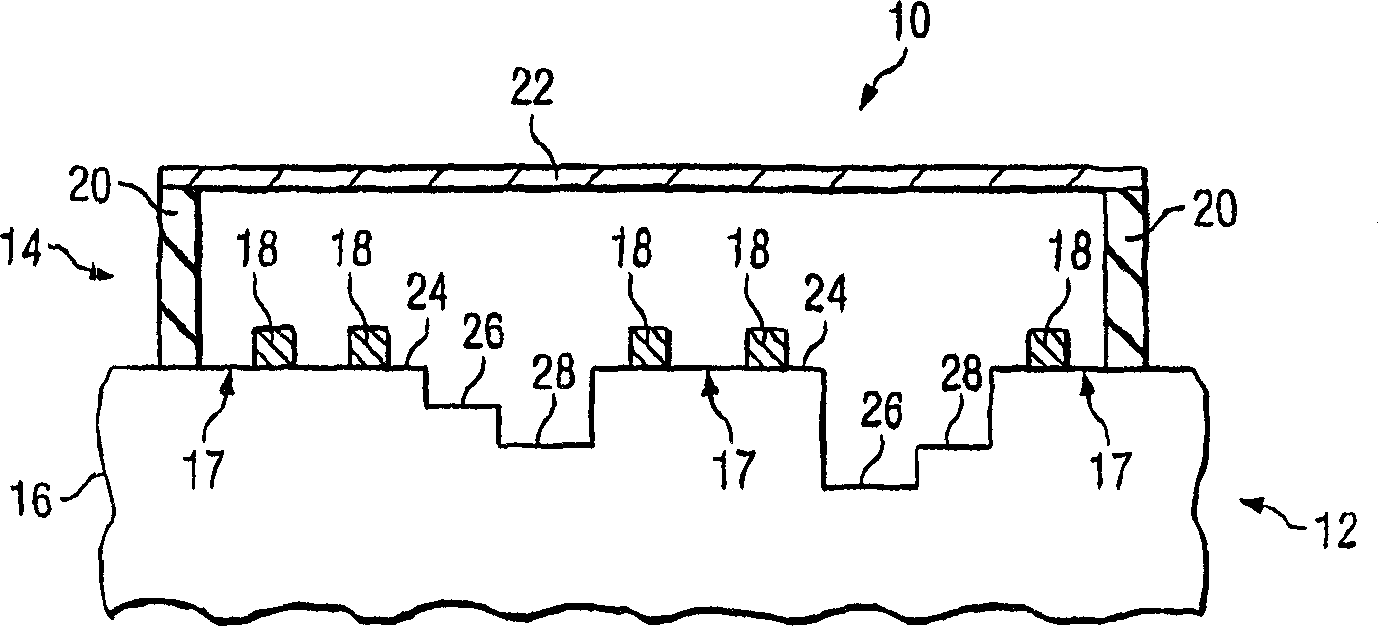
[0024] figure 1 A cross-sectional view of an exemplary photomask assembly 10 is shown. Photomask assembly 10 includes pellicle assembly 14 mounted on photomask 12 . The phase shift window (PSW) 24 of substrate 16, pattern layer 18, 0 degree, orthogonal PSW 26 and 180 degree PSW 28 forms photomask 12, and photomask 12 is called reticle or mask again, it Available in a variety of sizes and shapes including, but not limited to, round, rectangular, and square. The photomask 12 can also be any photomask including, but not limited to, a one-time master mask, a five-inch reticle, a six-inch reticle, a nine-inch reticle, or any other reticle that can be used to pattern a circuit A reticle of the appropriate size is projected onto a se...


PUM

PropertyMeasurementUnit
wavelengthaaaaaaaaaa

Abstract

A phase shift photomask and method for improving printability of a structure on a wafer are disclosed. The method includes providing a photomask including a zero degree PSW formed on a top surface of a substrate and a 180 degree PSW formed in a first region of the substrate. An orthogonal PSW that facilitates projection of an increased intensity of radiant energy through a second region of the substrate during a lithography process is formed in the second region between the zero degree PSW and the 180 degree PSW.

Description

[0001] related application [0002] This application claims the title "PHASE SHIFTPHOTOMASK AND METHOD FOR IMPROVING PRINTABILITY OFA STRUCTURE ON A WAFER"), U.S. Provisional Patent Application Serial No. 60 / 520,809. [0003] This application also claims the title "PHASESHIFT PHOTOMASK AND METHOD FOR IMPROVING PRINTABILITY OF A STRUCTURE ON", filed April 30, 2004 by Kent Nakagawa A WAFER"), U.S. Provisional Patent Application Serial No. 60 / 566,733. technical field [0004] The present invention relates generally to photolithographic methods and, more particularly, to phase shift photomasks and methods for improving the printability of structures on wafers. Background technique [0005] As device manufacturers reduce the size of the devices they produce, so do the demands placed on the photomasks used in the fabrication of these devices. A photomask (also referred to as a reticle or mask) generally consists of a substrate on which a pattern layer is formed. The absorber l...

Claims


Application Information

Patent Timeline
Patent Type & Authority Applications(China)
IPC IPC(8): G01F9/00G03F9/00G03C5/00
Inventor K·纳卡加瓦
Owner 凸版光掩公司
Why Eureka
Try Eureka