
Detachable hollow fiber membrane module

A fiber membrane and hollow technology, applied in the field of detachable hollow fiber membrane modules, can solve the problems of inconvenient industrialization, low plasticity, uneven distribution of air flow field, etc., and achieve the effect of sufficient heat and mass exchange

Pending Publication Date: 2020-02-04
GUILIN UNIV OF ELECTRONIC TECH
View PDF3 Cites 0 Cited by
  • Summary
  • Abstract
  • Description
  • Claims
  • Application Information

AI Technical Summary

Problems solved by technology

[0006] To sum up, in order to overcome the disadvantages of uneven air flow field distribution, inability to disassemble and replace, low plasticity, difficulty in large-scale preparation and inconvenient realization of industrialization in the prior art, the problems to be solved by the present invention The technical problem is to provide a detachable hollow fiber membrane module

Method used


Image

  • Detachable hollow fiber membrane module
  • Detachable hollow fiber membrane module
  • Detachable hollow fiber membrane module

Examples


Embodiment 1

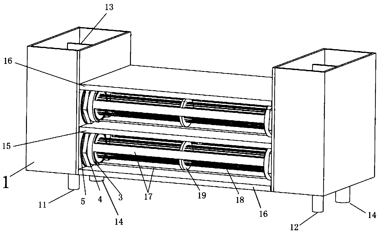
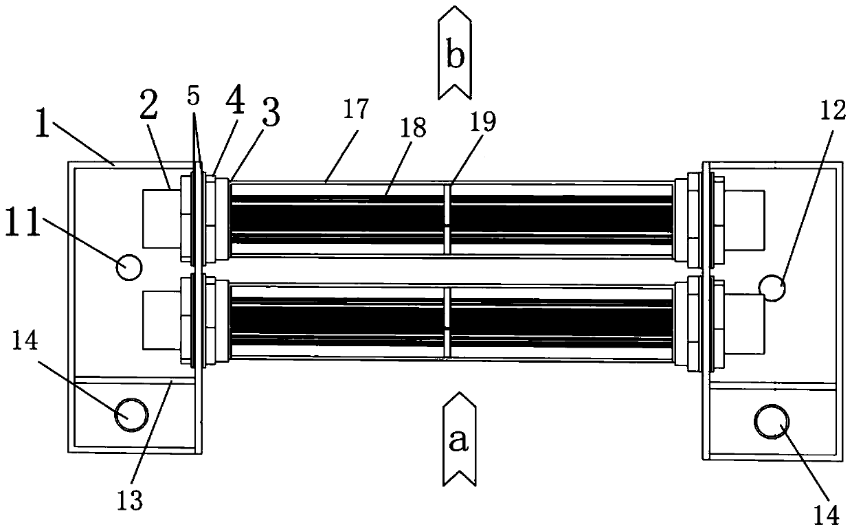
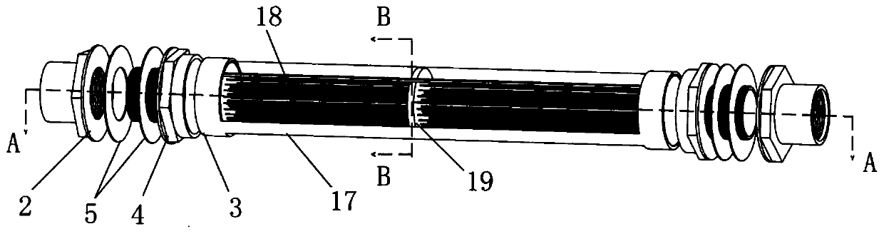
[0040] like figure 1 and 2 As shown, a detachable hollow fiber membrane module includes a solution tank 1, a hollow fiber membrane tube bundle, a first joint 2, a shell 3 and a second joint 4. There are two solution tanks 1, which are respectively opposite to the outer sides of both ends of the hollow fiber membrane tube bundle. The solution tank 1 is filled with cold water or liquid desiccant. The first joint 2 is fixed on the solution tank 1 at a position corresponding to the end of the tube bundle. Both ends of the hollow fiber membrane tube bundle are respectively fixed in different shells 3 . The two ends of the second joint 4 are respectively connected with the first joint 2 and the housing 3 by screws to realize the detachable communication between the tube bundle and the solution tank 1.

[0041] The inner side wall of the first joint 2 is provided with an inner thread, and the outer side wall of the housing 3 is provided with an outer thread. The outer side wall ...

Embodiment 2

[0052] like Figure 8 As shown, a third joint 6, a fourth joint 7, a connecting pipe 8, a valve 9 and a support plate 10 are added, the third joint 6 is screwed to the first joint 2, and the fourth joint 7 is screwed to the For the second joint 4 , two ends of the connecting pipe 8 are respectively connected to the third joint 6 and the fourth joint 7 by screwing. The valve 9 is arranged on the connecting pipe 8 and is used for connecting or disconnecting the connecting pipe 8. The support plate 10 is fixed at the position where the second joint 4 and the fourth joint 7 are connected and are connected to each other. play a supporting role. The first joint 2 , the second joint 4 , the third joint 6 and the fourth joint 7 are respectively provided with polygonal discs that rotate the corresponding joints. Between the joint 2 and the corresponding inner wall of the solution tank 1, between the third joint 6 and the corresponding outer wall of the solution tank 1, between the fo...


PUM


Abstract

The invention relates to a detachable hollow fiber membrane module. The detachable hollow fiber membrane module includes two solution tanks, hollow fiber membrane tube bundles, first joints, shells and second joints. The two solution tanks are oppositely arranged on the outer sides of two ends of the hollow fiber membrane tube bundles separately; cold water or liquid desiccant is installed in thesolution tanks; the first joints are fixed to the solution tanks and correspond to the positions of the end parts of the tube bundles; both ends of the hollow fiber membrane tube bundles are separately fixed into the different shells; and the two ends of the second joint are in threaded connection with the first joints and the shells separately to realize detachable communication between the tubebundles and the solution tanks. The detachable hollow fiber membrane module has the beneficial effects that the hollow fiber membrane tube bundles can be detachably fixed between the two solution tanks through the first joints and the second joints, so that the hollow fiber membrane tube bundles are disassembled and assembled at any time, and the hollow fiber membrane tube bundles can be put in asolution to perform heat and mass exchange with air in an air duct more fully.

Description

technical field [0001] The invention relates to a hollow fiber membrane assembly, in particular to a detachable hollow fiber membrane assembly. Background technique [0002] People spend 70% to 90% of their life indoors, so people pay more and more attention to the indoor air environment. The earliest people only paid attention to the temperature parameters in the air environment, but humidity, like temperature, also plays an important role in the comfort and health of the human body. An air environment with too high or too low humidity also accelerates the release of chemicals (formaldehyde and ozone) from indoor building materials, and accelerates the growth and reproduction of microorganisms such as viruses, fungi and bacteria, and these chemicals can seriously affect our health. The standards for healthy houses specified in detail by the World Health Organization, in which the indoor temperature and humidity have given specific numerical ranges, the regulations point ou...

Claims


Application Information

Patent Timeline
Patent Type & Authority Applications(China)
IPC IPC(8): B01D63/02B01D53/26
CPCB01D53/268B01D63/02B01D2257/80B01D2258/06
Inventor 梁才航何智鹏雷滕跃
Owner GUILIN UNIV OF ELECTRONIC TECH
Features
  • Generate Ideas
  • Intellectual Property
  • Life Sciences
  • Materials
  • Tech Scout
  • Unparalleled Data Quality
  • Higher Quality Content
  • 60% Fewer Hallucinations
Learn More