
Vertical pipe evaporative type condensing heat exchanger with repeated water distribution function and heat exchange method thereof

An evaporative condenser and heat exchanger technology, which is applied in steam/steam condensers, lighting and heating equipment, etc., can solve the problems of making breakthroughs in the heat transfer effect of evaporative condensers, and achieve the technical means that are simple and easy to implement and reduce spraying. Water temperature, increase the effect of disturbance

Pending Publication Date: 2018-03-16
SOUTH CHINA UNIV OF TECH
View PDF11 Cites 0 Cited by
  • Summary
  • Abstract
  • Description
  • Claims
  • Application Information

AI Technical Summary

Problems solved by technology

At this stage, the heat transfer effect of the evaporative condenser has been greatly improved by using various enhanced heat transfer tubes such as elliptical tubes and twisted tubes to replace the existing smooth round tubes, and using nanofluid technology; Based on tubes, it is difficult to make a breakthrough in technology to improve the heat transfer effect of evaporative condensers

Method used


Image

  • Vertical pipe evaporative type condensing heat exchanger with repeated water distribution function and heat exchange method thereof
  • Vertical pipe evaporative type condensing heat exchanger with repeated water distribution function and heat exchange method thereof
  • Vertical pipe evaporative type condensing heat exchanger with repeated water distribution function and heat exchange method thereof

Examples


Embodiment

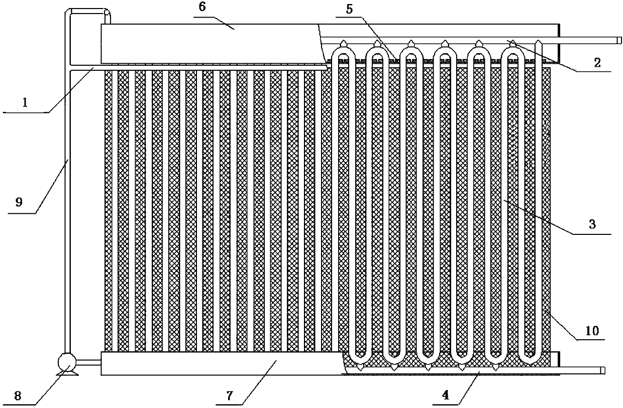
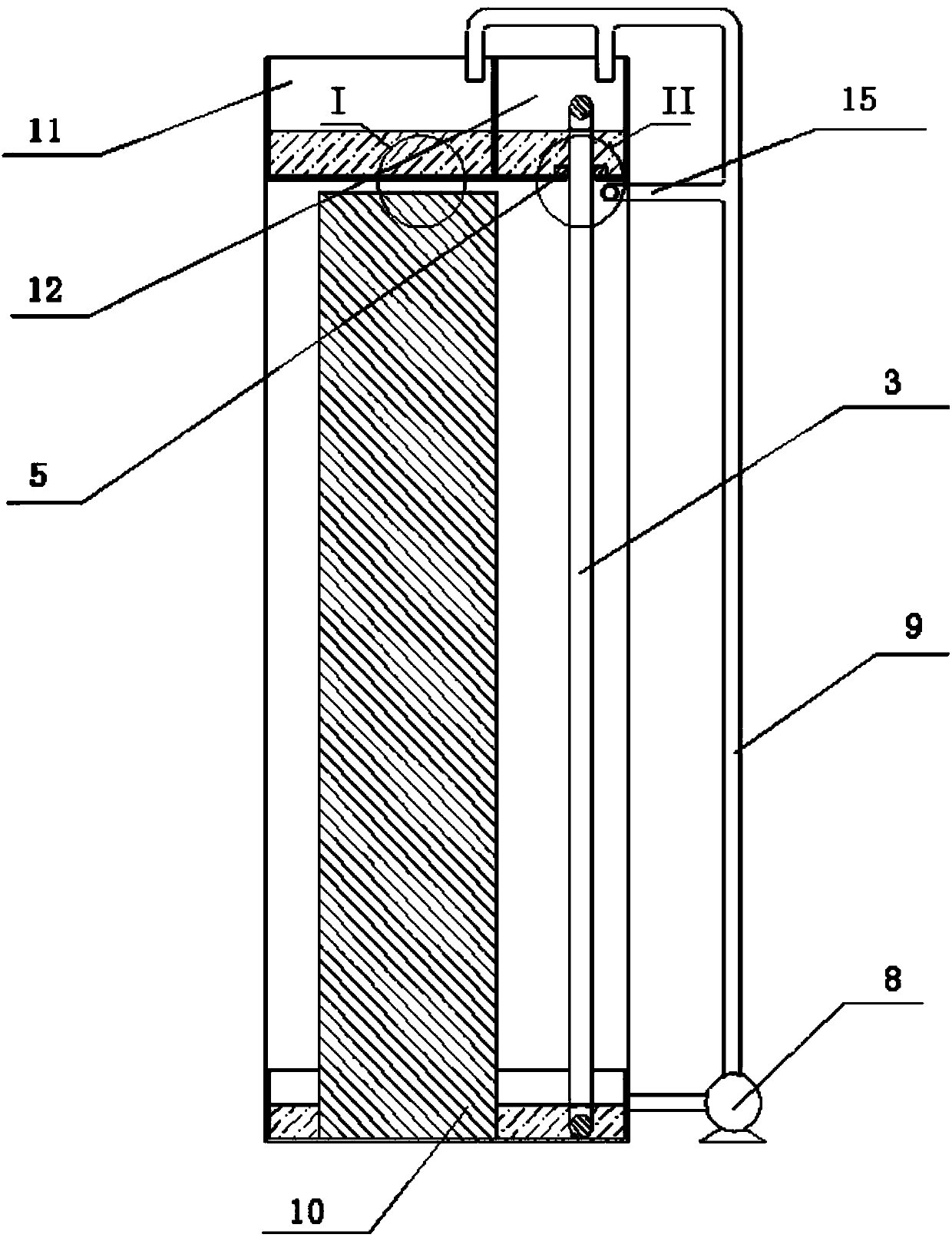
[0031] Such as Figures 1 to 4 shown. The invention discloses a vertical pipe evaporative condensing heat exchanger with multiple water distributions, which comprises an upper gas collecting pipe 2, a lower liquid collecting pipe 4, and vertical condensing heat exchange pipes 3 arranged in a vertical array; the vertical The upper end of the condensing heat exchange tube 3 communicates with the upper gas collector 2, and the lower end communicates with the lower liquid collector 4; the axis of the vertical condensing heat exchange tube 3 is perpendicular to the upper gas collector 2 and the lower liquid collector 4; it is characterized in that: A liquid separator 6 is arranged above the condensing heat exchange tube 3, and a liquid collector 7 is arranged below; the liquid separator 6 divides its interior into a first liquid separator 11 and a second liquid separator 12 through a partition;

[0032] The water below the liquid collecting pan 7 is transported to the first liquid...


PUM


Abstract

The invention discloses a vertical pipe evaporative type condensing heat exchanger with a repeated water distribution function and a heat exchange method thereof. A fluid distribution plate is arranged above vertical condensing heat exchange pipes, and a fluid collecting plate is arranged below the vertical condensing heat exchange pipes. The interior of the fluid distribution plate is divided into a first fluid distribution plate body and a second fluid distribution plate body by a partition plate. A filler layer is arranged on the leeward sides of the vertical condensing heat exchange pipesand above the fluid collecting plate, and the upper end of the filler layer extends to a micro-porous array area of the bottom of the first fluid distribution plate body. The bottom of the second fluid distribution plate body is provided with diversion water distribution holes allowing pipe bodies of the upper ends of the vertical condensing heat exchange pipes to extend into. A water distributionpipe is further provided with a branch pipeline, and nozzle arrays are distributed on the branch pipeline at intervals. Nozzles of the nozzle arrays spray water right opposite to the windward sides of the upper ends of the vertical condensing heat exchange pipes, and water drops sprayed by the nozzle arrays are overlapped on the surface of a fluid film to perform disturbance on the fluid film. The heat exchanger can greatly improve the condensing heat exchange performance of refrigerating fluid and the overall performance of a unit and is relatively easy to process and manufacture and low incost.

Description

technical field [0001] The invention relates to an evaporative condenser, in particular to a vertical tube evaporative condensation heat exchanger with multiple water distribution and a heat exchange method thereof. Background technique [0002] The main working principle of the evaporative condenser is to condense the refrigerant vapor in the heat exchange tube through the latent heat generated by the evaporation of cooling water sprayed outside the heat exchange tube. It combines the cooling and heat exchange process of the water cooling of the traditional water cooling unit and the cooling and heat exchange process of the air cooling cooling tower, which saves the heat exchange equipment in the intermediate process and reduces the initial investment of the equipment; it has high heat transfer efficiency, compact structure and small volume , less circulating water, and are increasingly widely used in power, chemical, food, petrochemical, refrigeration and other industries....

Claims


Application Information

Patent Timeline
IPC IPC(8): F28B1/02F28B9/04
CPCF28B1/02F28B9/04
Inventor 刘金平魏俊卿阮建高梁灵娇
Owner SOUTH CHINA UNIV OF TECH
Features
  • Generate Ideas
  • Intellectual Property
  • Life Sciences
  • Materials
  • Tech Scout
  • Unparalleled Data Quality
  • Higher Quality Content
  • 60% Fewer Hallucinations
Learn More