
Mirror frame pulp wrapping machine

A technology of hanging pulp machine and mirror frame, which is applied in the directions of liquid injection device, pretreatment surface, injection device, etc., can solve the problems of increasing manufacturing cost, wasting pulp, uneven coating on the surface of the mirror frame, etc., to accelerate the solidification speed and save money. cost, and the effect of improving the efficiency of hanging pulp

Pending Publication Date: 2020-02-04
江苏森宝节能材料有限公司
View PDF0 Cites 2 Cited by
  • Summary
  • Abstract
  • Description
  • Claims
  • Application Information

AI Technical Summary

Problems solved by technology

[0003] And the picture frame of the mirror mostly is to use wooden bar or foaming material to make, hang paste on the surface of the picture frame, then after the paste is solidified, engrave lines on the surface of the solidification, so that the picture frame becomes beautiful, but the existing Technology The method of coating the frame is relatively simple, which often makes the surface of the frame uneven and needs to be polished, which wastes a lot of slurry and increases the manufacturing cost.

Method used


Image

  • Mirror frame pulp wrapping machine
  • Mirror frame pulp wrapping machine
  • Mirror frame pulp wrapping machine

Examples


Embodiment Construction

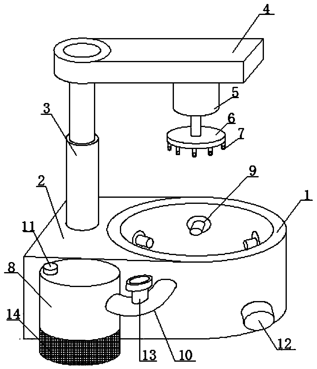
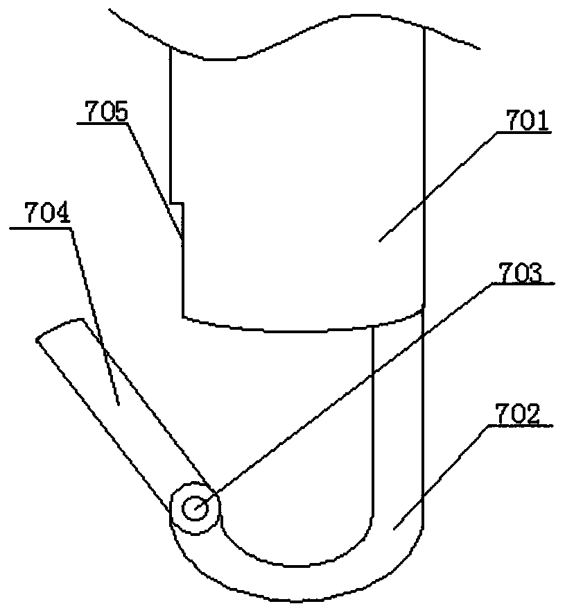
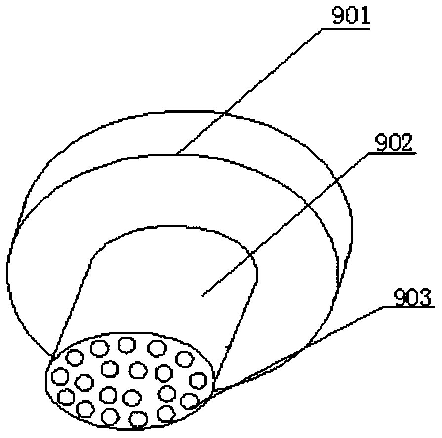
[0023] Embodiments of the present invention provide a frame hanger, such as Figure 1-5 As shown, including the slurry tank 1, the left side of the slurry tank 1 is fixedly welded with an equipment platform 2, and the upper surface of the equipment platform 2 is fixedly welded with a telescopic rod 3, and the up and down movement of the picture frame is realized by the telescopic rod 3. The upper end is movably connected with a rotating plate 4, the lower surface of the rotating plate 4 is fixedly connected with a servo motor 5, the output end of the servo motor 5 is connected with a turntable 6, the lower surface of the turntable 6 is fixedly connected with a hook 7, and the side of the equipment table 2 A slurry tank 8 is provided, a booster pump 14 is provided on the lower surface of the slurry tank 8, the slurry tank 8 communicates with the slurry tank 1 through a feed pipe 10, and a control valve 13 is provided on the outer surface of the feed pipe 10 The inner wall of th...


PUM


Abstract

The invention provides a mirror frame pulp wrapping machine, and relates to the technical field of mirror frame processing. The mirror frame pulp wrapping machine comprises a pulp wrapping bath, an equipment table is fixedly welded to the left side of the pulp wrapping bath, the upper surface of the equipment table is fixedly provided with a telescopic rod in a welded mode, the upper end of the telescopic rod is fixedly connected with a servo motor through a rotating plate, the output end of the servo motor is fixedly connected with a hook through a rotating disc, a pulp barrel is arranged onthe side face of the equipment table, a booster pump is arranged on the lower surface of the pulp barrel, the pulp barrel communicates with the pulp wrapping bath through a material guiding pipe, anda nozzle is fixedly connected to the inner wall of the pulp wrapping bath. According to the mirror frame pulp wrapping machine, the booster pump and the servo motor are started, so that a pulp machinesends pulp to a material feeding pipe, the pulp is finally sprayed out from the nozzle through the material guide pipe, and pulp wrapping is carried out on the surface of a mirror frame; and moreover, the rotating disc starts to rotate, so that the pulp is uniformly wrapped around the outer surface of the mirror frame, the mirror frame moves relative to air in the rotating process, then the solidification speed of pulp wrapping is accelerated, and the pulp wrapping efficiency is improved.

Description

technical field [0001] The invention relates to the technical field of photo frame coating, in particular to a photo frame coating machine. Background technique [0002] In daily life, we often need to use mirrors, and mirrors are not only used as a tool, but also play a decorative role in home decoration. Usually, the reason why we choose mirrors is to compare the frames of mirrors. favorite. [0003] And the picture frame of the mirror mostly is to use wooden bar or foaming material to make, hang paste on the surface of the picture frame, then after the paste is solidified, engrave lines on the surface of the solidification, so that the picture frame becomes beautiful, but the existing Technology The way to paste the frame is relatively simple, which often makes the surface of the frame uneven and needs to be polished, which wastes a lot of paste and increases the manufacturing cost. Contents of the invention [0004] (1) Solved technical problems [0005] Aiming at t...

Claims


Application Information

Patent Timeline
Patent Type & Authority Applications(China)
IPC IPC(8): B05B9/04B05B13/02B05B14/00B05D3/04
CPCB05B9/0423B05B13/0228B05B13/0264B05B14/00B05D3/0406
Inventor 齐瑞环
Owner 江苏森宝节能材料有限公司
Learn More