Central gunite spraying system for multiple pig iron casting machine production lines

A cast iron machine and production line technology, applied in casting molding equipment, surface coating liquid devices, metal processing equipment, etc., can solve the problems of low slurry utilization rate, complicated operation and maintenance, unsatisfactory demoulding, etc., and achieve slurry High material utilization rate, uniform slurry coating, good spraying and mold release effects

Pending Publication Date: 2020-06-30
山西建邦集团铸造有限公司
View PDF0 Cites 0 Cited by
  • Summary
  • Abstract
  • Description
  • Claims
  • Application Information

AI Technical Summary

Problems solved by technology

[0004] In view of this, the object of the present invention is to provide a central spraying system for multiple cast iron machine production lines, aiming to overcome the complex operation and maintenance, high power consumption, low slurry utilization and Unsatisfactory demoulding defects

Method used


Image

  • Central gunite spraying system for multiple pig iron casting machine production lines

Examples


Embodiment 1

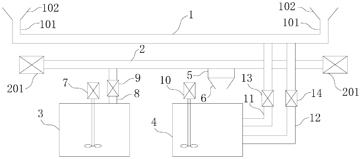
[0018] Such as figure 1 As shown, the central spraying system used for multiple cast iron production lines includes a main spraying pipeline 1, a slurry return channel 2 is provided under the main spraying channel 1, and a slurry mixing channel is provided below the return channel 2 Tank 3 and slurry storage tank 4;

[0019] The two ends of the spraying main pipe 1 are provided with several spraying branch pipes 101 leading to different cast iron machines, the spraying branch pipes 101 are provided with nozzles 102, and the slurry in the spraying branch pipes 101 passes through the nozzles 102 to The mold cavity of the cast iron chain belt is sprayed, and the slurry return channel 2 is suitable for receiving excess slurry flowing down from the mold cavity of the cast iron belt belt and the nozzle 102. The lower end of the slurry return channel 2 is provided with a high frequency screen 5, and the high frequency The screen 5 is set directly above the slurry storage tank 4, and...

Embodiment 2

[0023] Based on the structure of Example 1, in Example 2, both the slurry storage tank 4 and the slurry mixing tank 3 are of cement concrete structure, and the capacity of the slurry storage tank 4 and the slurry mixing tank 3 is relatively large.

Embodiment 3

[0025] Based on the structure of Embodiment 1, in Embodiment 3, two spraying branch pipes 101 are provided, and they are arranged symmetrically at both ends of the main spraying pipe 1 .

[0026] When working, the slurry in the slurry mixing tank 3 is sent to the slurry return channel 2 through the slurry replenishing pump 9 in the slurry mixing tank 3 after the first stirring reducer 7 performs the first slurry stirring, and then the slurry is sent to the return channel 2 by the high frequency The sieve 5 vibrates to separate the pure slurry in the slurry, and the pure slurry enters the slurry storage tank 4 from the slurry return tank 6 at the lower part of the high-frequency sieve 5, and the slurry storage tank 4 performs the second stirring under the operation of the second stirring reducer 10. Stir evenly for the first time, and the viscosity is moderate, then the slurry in the slurry storage tank 4 is pumped into the main pipeline 1 of the slurry by the slurry pump 14, an...


PUM


Abstract

The invention discloses a central gunite spraying system for multiple pig iron casting machine production lines. The central gunite spraying system comprises a gunite spraying main pipeline, wherein agunite return channel is arranged below the gunite spraying main pipeline, and a gunite storage pool and a gunite mixing pool are arranged below the gunite return channel; a plurality of gunite spraying branch pipes are arranged at the two ends of the gunite return channel, a high-frequency screen is arranged at the lower end of the gunite return channel, blow-down valves are arranged at the twoends of the gunite return channel, and a gunite return groove is connected to the lower portion of the high-frequency screen; a first stirring speed reducer is arranged in the gunite mixing pool, wherein the upper end of the gunite mixing pool is connected with a first gunite pipe, a gunite supplementing pump is arranged on the first gunite pipe, and the other end of the first gunite pipe communicates with the gunite return channel; and a second stirring speed reducer is arranged in the gunite storage pool, the side end of the gunite storage pool is sequentially connected with a second gunitepipe and a third gunite pipe from top to bottom, a pressure regulating valve is arranged on the second gunite pipe, a gunite spraying pump is arranged on the third gunite pipe, and the other end of the second gunite pipe and the other end of the third gunite pipe communicate with the gunite spraying main pipeline. The central gunite spraying system is convenient to maintain, high in gunite utilization rate, free of impurities, good in spraying effect and low in power consumption and equipment cost.

Description

technical field [0001] The invention relates to cast iron machine equipment in the blast furnace smelting production process, in particular to a central spraying system for a plurality of cast iron machine production lines. Background technique [0002] In the production of modern metallurgical cast iron enterprises, the amount of molten iron produced by one blast furnace corresponds to two or more cast iron machine production lines for casting iron. Each cast iron machine production line includes two cast iron chain belts and a set of spraying system. The spraying system of the cast iron machine consists of three parts: pulping, spraying and recycling. The two self-priming non-clogging sewage pumps of the spraying system first suck out the mixed slurry with uniform mixing and moderate viscosity from the mixing device, and send it to the bottom of the two cast iron chain belts through the spraying pipe, and the nozzle sends the mixed slurry to the cast iron mold. The inner ...

Claims


Application Information

Patent Timeline
Patent Type & Authority Applications(China)
IPC IPC(8): B22C23/02B05D1/02
CPCB05D1/02B22C23/02
Inventor 韩军华尚小虎常东军
Owner 山西建邦集团铸造有限公司
Why Eureka
Try Eureka