
Heat radiation structure of air conditioner

A technology for air conditioners and electronic components, which is applied in the field of heat release structures and can solve problems such as differences in insulation effects

Inactive Publication Date: 2007-11-28
LG ELECTRONICS (TIANJIN) APPLIANCES CO LTD
View PDF0 Cites 0 Cited by
  • Summary
  • Abstract
  • Description
  • Claims
  • Application Information

AI Technical Summary

Problems solved by technology

In this way, the insulation effect will vary with different parts

Method used


Image

  • Heat radiation structure of air conditioner
  • Heat radiation structure of air conditioner
  • Heat radiation structure of air conditioner

Examples


Embodiment Construction

[0031] First of all, air conditioners are divided into: a single system in which indoor units and outdoor units are connected one-to-one, and a one-to-multiple system in which multiple indoor units share one outdoor unit.

[0032] Whether it is a single system or a multi-system system, a microprocessor is built in the indoor unit. The microprocessor receives user input commands and generates corresponding control signals. The indoor unit is further provided with a communication unit. The indoor unit and the outdoor unit transmit and receive signals through the communication unit.

[0033] In the same way, whether it is a single system or a multi-system system, a microprocessor is built in the outdoor unit. The microprocessor controls the circulation direction and distribution amount of the refrigerant according to the above-mentioned control signal. In addition, the outdoor unit is further provided with a communication unit. The indoor unit and the outdoor unit transmit an...


PUM


Abstract

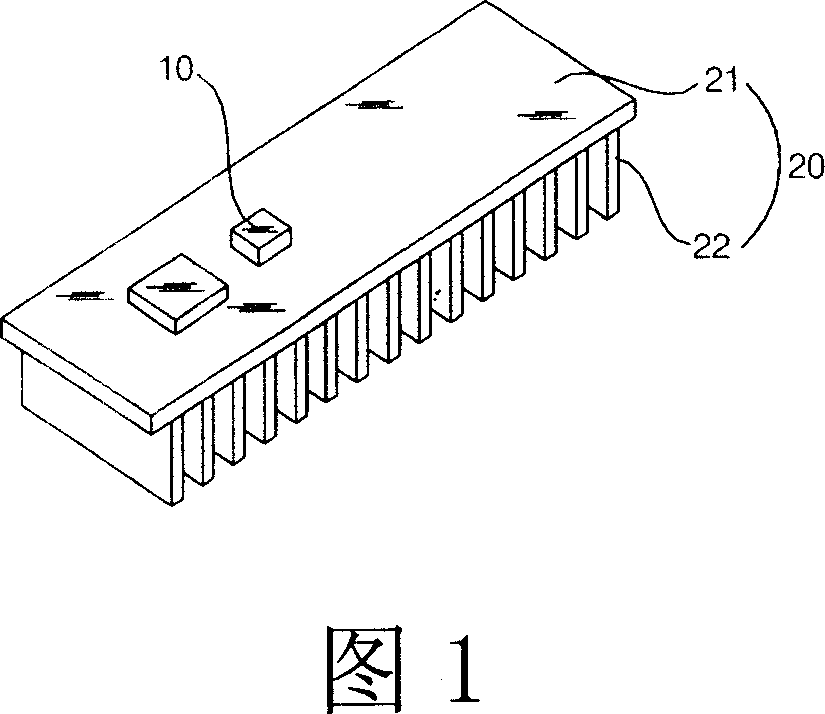
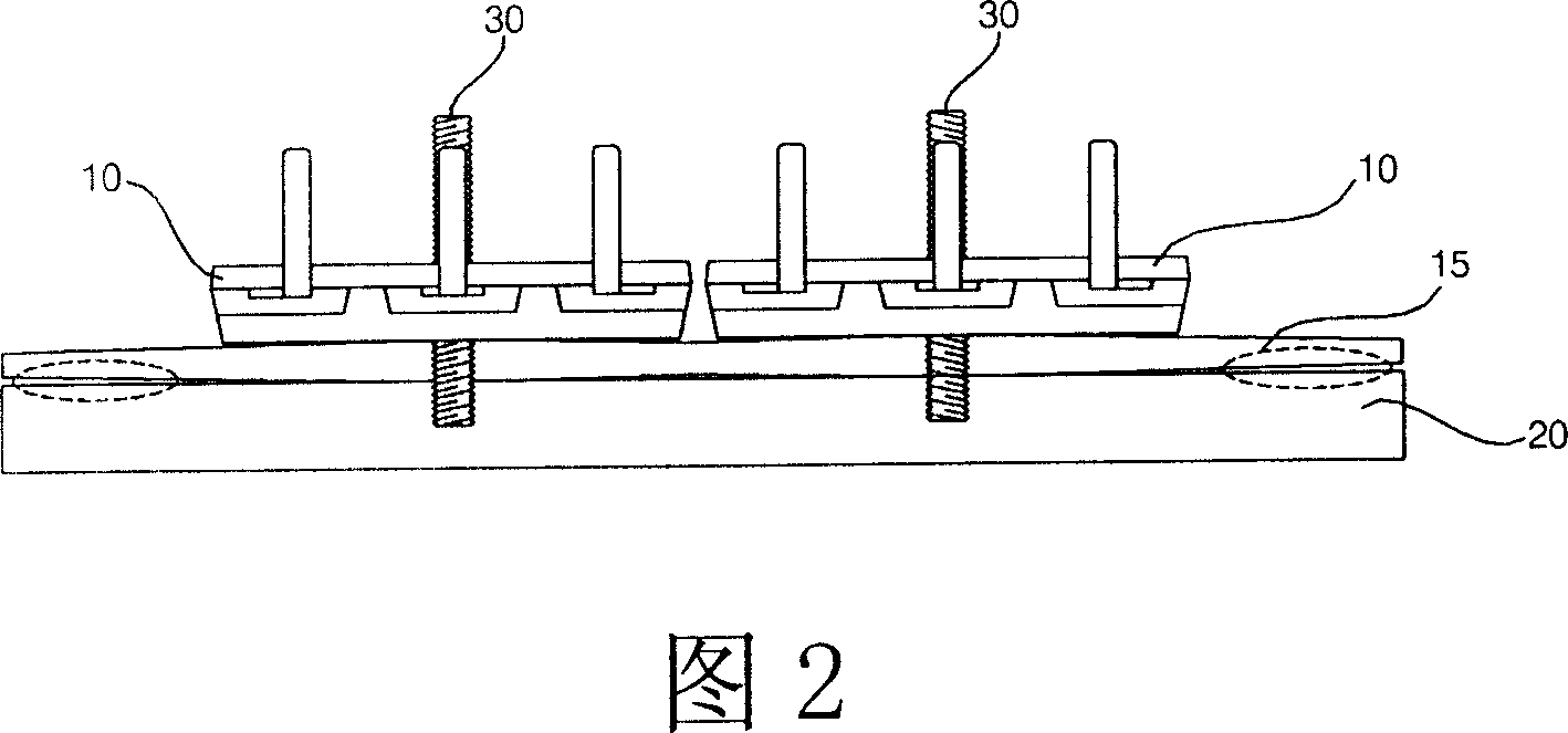
This invention relates to a heat-discharge structure of an air-conditioner including: more than one electronic heating parts set in the outdoor or the indoor machine, heat discharge plates set adjacent to the parts for radiating heat generated by them, heat discharging pads for insulation and set between the electronic parts and the heat discharge plates, in which, double-face adhesive tapes are adhered on both sides of the pads contacted with the parts and the plates, and the heat discharge plate is made of Al and composed of a chassis adjacent to the electronic parts and multiple heat discharge pins vertical to the surface of the chassis.

Description

technical field [0001] The invention relates to a heat releasing structure of an air conditioner. Background technique [0002] Generally speaking, the function of the air conditioner is as follows: In the season of high temperature, the air conditioner sucks the hot air in the room, cools the hot air into cold air through heat exchange, and discharges the cold air back into the room, so that the room can be cooled. temperature dropped. The air conditioner with the above functions is composed of the following components: compressor, condenser, evaporator, expansion device and many other components that constitute the refrigeration cycle; fan. [0003] The working principle of the above-mentioned air conditioner is roughly as follows: the gas refrigerant in the low-temperature and low-pressure state is compressed by the compressor into a high-temperature and high-pressure state, and then the compressed gas refrigerant in the high-temperature and high-pressure state is coole...

Claims


Application Information

Patent Timeline
Patent Type & Authority Applications(China)
IPC IPC(8): H05K7/20F24F13/00
Inventor 郑炳华
Owner LG ELECTRONICS (TIANJIN) APPLIANCES CO LTD
Learn More