Circuit device

A circuit device and circuit technology, which can be applied to circuits, lighting devices, discharge lamps, etc., can solve the problems of high cost-effectiveness and shortening the life of circuit devices.

Inactive Publication Date: 2003-04-30
KONINKLIJKE PHILIPS ELECTRONICS NV
View PDF4 Cites 0 Cited by
  • Summary
  • Abstract
  • Description
  • Claims
  • Application Information

AI Technical Summary

Problems solved by technology

This high current will shorten the lifetime of the circuit device, or, depending on the high current needs to increase the size of the circuit device, which makes the equivalent expensive
Another disadvantage of the known circuit devices is that they usually contain a frequ...

Method used


Image

  • Circuit device
  • Circuit device
  • Circuit device

Examples


Embodiment Construction

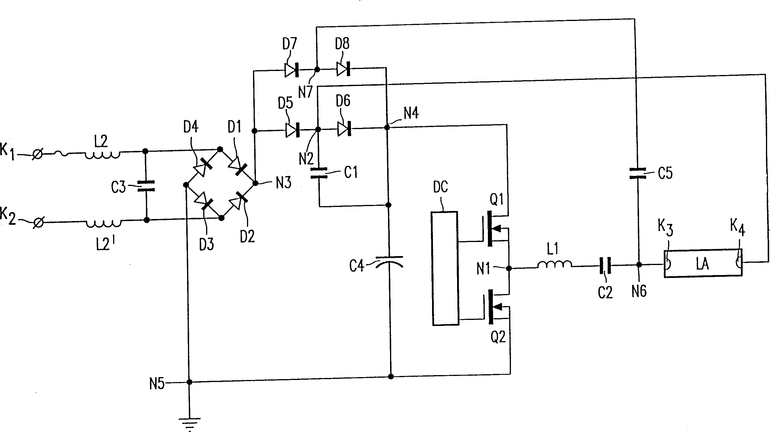
[0023] figure 1 Among them, K1 and K2 are the input terminals connected to the low-frequency power supply. L2 and L2' are inductors, which together with capacitor C2 form an input filter circuit. Diodes D1-D4 are rectifiers for rectifying low-frequency power. Current C4 is the first capacitor, which together with diodes D5 and D6 forms the first circuit. The switching elements Q1 and Q2 together with the driving circuit DC form a frequency converter. The drive circuit DC0 is a part of the circuit that generates a drive signal, and uses the drive signal to control the conduction and non-conduction of the switching elements Q1 and Q2. The inductor L1, the capacitor C2, and the terminals K3 and K4 connected to the discharge lamp together form a load circuit. in the attached figure 1 In the embodiment shown, the inductor L1 forms the inductor, the capacitor 2 forms the second capacitor, and the connection terminals K3 and K4 form the voltage supply for the discharge lamp. Ca...


PUM


Abstract

A circuit arrangement for operating a discharge lamp with a high frequency current comprising input terminals for connection to a source of low frequency supply voltage, a rectifier bridge coupled to the input terminals for rectifying the low frequency supply voltage, and an inverter shunting a first capacitor for generating the high frequency current. The circuit arrangement incorporates two power feedback loops to feed power back to an output terminal of the rectifier bridge. As a result the circuit arrangement has a relatively simple configuration, causes only a very limited amount of harmonic distortion and can be realized with relatively cheap and simple components.\!

Description

technical field [0001] The invention relates to a circuit device, which provides a high-frequency operating current for a discharge lamp, comprising the following parts: [0002] - the input terminal to which the low frequency supply voltage is connected, [0003] - rectifiers connected to the input terminals for rectifying low-frequency supply voltages, [0004] - a first circuit comprising a first unidirectional device, a second unidirectional device and a first capacitor connected between the first output terminal N3 and the second output terminal N5 of the rectifier, [0005] - a frequency converter associated with the first capacitor for generating high-frequency currents, [0006] - a load circuit comprising an inductor, a second capacitor and a device for supplying a voltage to the discharge lamp, which connect terminal N1 of the frequency converter with another terminal N2 between the first unidirectional device and the second between one-way devices. [0007] - A ...

Claims


Application Information

Patent Timeline
IPC IPC(8): H05B41/282H05B41/28H05B41/295
CPCY10S315/07H05B41/28H05B45/355H05B41/282
Inventor A·F·J·赫尔纳德兹·马托希J·H·范比仁P·J·兹尔斯特拉
Owner KONINKLIJKE PHILIPS ELECTRONICS NV
Why Eureka
Try Eureka