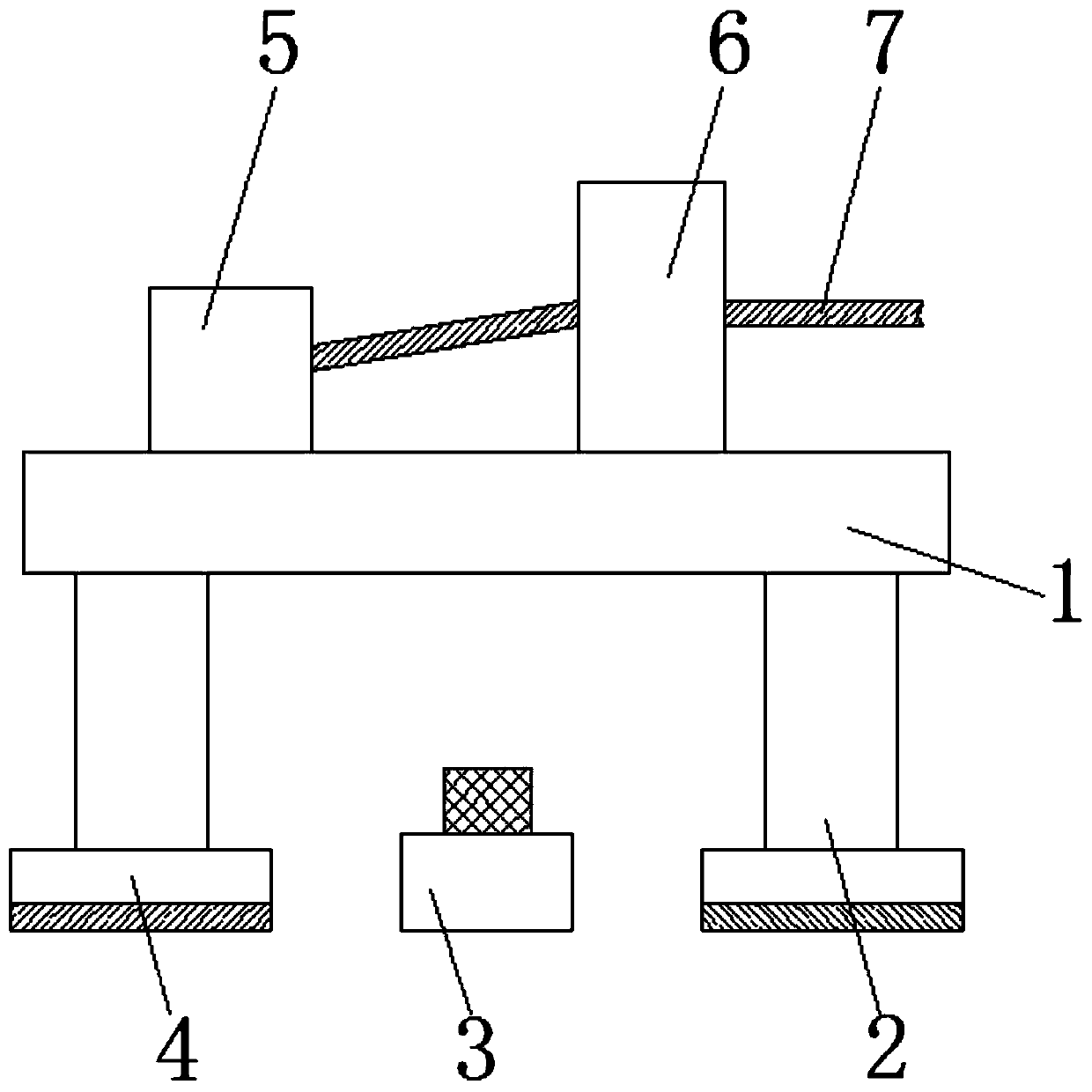
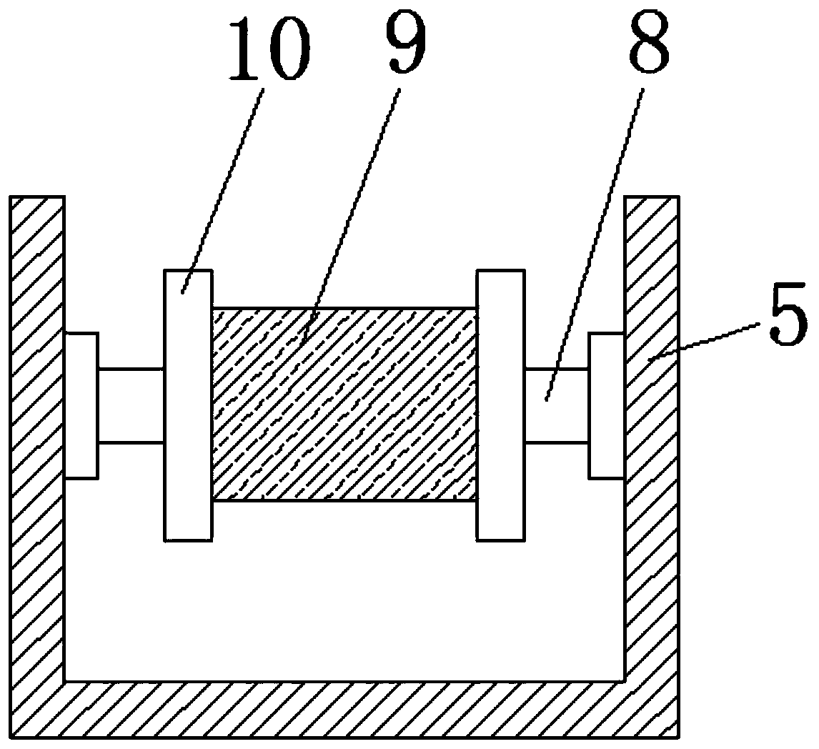
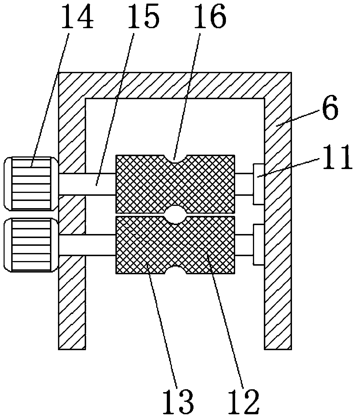
Wire feed device with tread control wire feed structure and of welding wire feeder

A wire feeder and wire feeder technology, which is applied to manufacturing tools, welding equipment, arc welding equipment, etc., can solve the problem of not having a foot-step control function, and achieve the effect of improving stability

Pending Publication Date: 2020-02-04
南京引力工业焊接技术研究院有限公司
View PDF0 Cites 0 Cited by
  • Summary
  • Abstract
  • Description
  • Claims
  • Application Information

AI Technical Summary

Problems solved by technology

[0004] The purpose of the present invention is to provide a wire feeding device with a pedal-type control wire feeding structure for a welding wire feeder, which has the advantages of a pedal-type control, and solves the problem that the welding wire feeder in the existing market does not have a pedal-type control function The problem

Method used


Image

  • Wire feed device with tread control wire feed structure and of welding wire feeder
  • Wire feed device with tread control wire feed structure and of welding wire feeder
  • Wire feed device with tread control wire feed structure and of welding wire feeder

Examples


Embodiment Construction

[0024] The following will clearly and completely describe the technical solutions in the embodiments of the present invention with reference to the accompanying drawings in the embodiments of the present invention. Obviously, the described embodiments are only some, not all, embodiments of the present invention. Based on the embodiments of the present invention, all other embodiments obtained by persons of ordinary skill in the art without making creative efforts belong to the protection scope of the present invention.

[0025] In the description of the invention, it should be noted that the terms "upper", "lower", "inner", "outer", "front end", "rear end", "both ends", "one end", "another end" etc. The indicated orientation or positional relationship is based on the orientation or positional relationship shown in the drawings, and is only for the convenience of describing the present invention and simplifying the description, rather than indicating or implying that the referre...


PUM


Abstract

The invention discloses a wire feed device with a tread control wire feed structure and of a welding wire feeder. The wire feed device comprises an operation table. The left side of the top of the operation table is fixedly connected with a wire storage frame. A moving roller is arranged in an inner cavity of the wire storage frame. A welding wire coil is wound in an inner cavity of the moving roller. The two sides of the moving roller are movably connected with moving shafts. Through the operation table, a control box, the wire storage frame, a wire feed frame, conveying rollers, stepping motors, rotating rods, a return spring, a press rod, a moving seat, a pedal and a circuit board, the device can achieve the tread control function, and the problems that in the current market, welding wire feeders have no tread control function, welding wire feed operation needs to be achieved by hands of users, workers hold welding guns by hand during welding work, wire feed cannot be operated in time, work needs to be stopped to carry out wire feed operation, continuity of welding work is influenced, and the situation is adverse to quality guarantees are solved.

Description

technical field [0001] The invention relates to the technical field of welding wire feeders, in particular to a wire feeding device with a pedal-type control wire feeding structure for a welding wire feeder. Background technique [0002] Welding wire is used as a filler metal or as a conductive wire welding material at the same time. In gas welding and tungsten gas shielded arc welding, welding wire is used as filler metal; in submerged arc welding, electroslag welding and other metal arc welding. , The welding wire is not only a filler metal, but also a conductive electrode, and the surface of the welding wire is not coated with anti-oxidation flux. [0003] In large-scale welding equipment, it is necessary to use a welding wire feeder to feed the welding wire. The existing welding wire feeder on the market does not have the function of stepping on the foot. The wire feeding operation of the welding wire needs to be operated by the user. During the welding operation, the h...

Claims


Application Information

Patent Timeline
IPC IPC(8): B23K9/133B23K9/12B23K9/173B23K9/18B23K25/00
CPCB23K9/124B23K9/133B23K9/1336B23K9/173B23K9/18B23K25/00
Inventor 浦娟时山奇王衍贺
Owner 南京引力工业焊接技术研究院有限公司
Why Eureka
Try Eureka