
Ceiling mounting structure and construction method

A technology for installing structures and ceilings, which is applied to building components, building structures, buildings, etc., can solve problems such as lack of effective support, simple ceiling installation structure, and poor ceiling stability, so as to improve installation stability and improve installation Convenience, the effect of a reliable connection

Active Publication Date: 2020-02-04
深圳市桦林达装饰设计工程有限公司
View PDF8 Cites 6 Cited by
  • Summary
  • Abstract
  • Description
  • Claims
  • Application Information

AI Technical Summary

Problems solved by technology

[0004] The above-mentioned existing technical solutions have the following defects: in the above-mentioned through-wire ceiling, the ceiling is only spliced ​​by relying on the steel frame of the keel and the visible surface of the keel, so that the installation structure of the ceiling is too simple and cannot be effectively supported. Poor stability

Method used


Image

  • Ceiling mounting structure and construction method
  • Ceiling mounting structure and construction method
  • Ceiling mounting structure and construction method

Examples


Embodiment 1

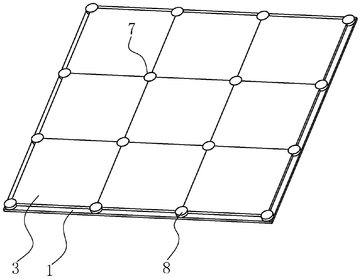
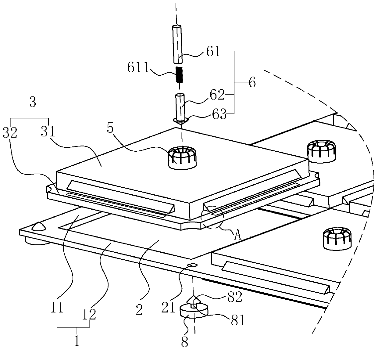
[0039] A ceiling-mounted structure that incorporates figure 1 with figure 2 , including a steel frame 1 located at a height of 50cm-70cm below the roof. The steel frame 1 includes multiple horizontal frames 11 parallel to each other and multiple vertical frames 12 parallel to each other. On the horizontal plane, the horizontal frame 11 and the vertical frame 12 are fixedly connected by welding, and the horizontal frame 11 and the vertical frame 12 are formed with a plurality of rectangular frame holes 2, and vertical connectors 6 are suspended on the roof, and the connectors 6 is located directly above the center of the frame hole 2, a ceiling body 3 is installed in the frame hole 2, the ceiling body 3 forms an insertion fit with the connector 6, and the ceiling body 3 forms a clip fit with the upper surface of the steel frame 1, thereby This makes the ceiling body 3 more stable after installation.

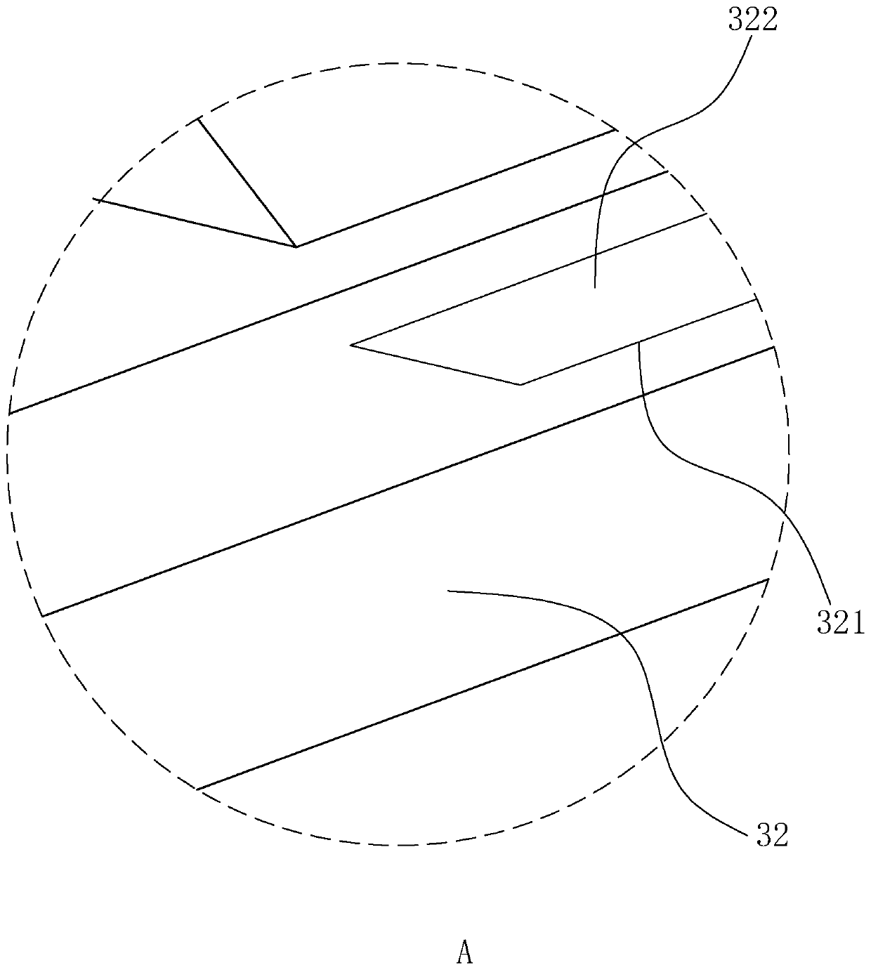
[0040] Such as figure 2 As shown, specifically, the ceiling body 3 inclu...

Embodiment 2

[0047] A kind of ceiling construction method, comprises the following steps:

[0048] S1. Install a steel frame 1 at a height of 50cm-70cm below the roof, install a plurality of connectors 6 on the roof, and each connector 6 faces the center of the frame hole 2;

[0049] S2. Install the ceiling body 3 upwards from the bottom of the frame hole 2, insert the inserting plate 31 into the frame hole 2 until the snap-in block 42 passes over the upper surface of the steel frame 1, and the snap-in block 42 is under the elastic restoring force of the return spring 43 Under the action, it abuts against the upper surface of the frame to form a snap fit, and the magnet block 322 is adsorbed on the lower surface of the steel frame 1, and at the same time, the plug joint 63 is inserted into the suspension column 5 to form a secondary snap fit;

[0050] S3. After the installation of every four adjacent ceiling bodies 3 is completed, insert the installation column 81 into the installation hol...


PUM


Abstract

The invention relates to a ceiling mounting structure and a construction method, and belongs to the technical field of interior decoration. The ceiling mounting structure is characterized in that theceiling mounting structure comprises a steel framework positioned on a roof and fixed to a wall body; the steel framework comprises a plurality of transverse frames and a plurality of longitudinal frames; the transverse frames and the longitudinal frames are perpendicular to each other and are positioned on the same horizontal plane; rectangular frame holes are formed between the transverse framesand the longitudinal frames; ceiling bodies are mounted in the frame holes; each ceiling body comprises an inserting plate which is inserted into the frame hole and a decorative plate which is fixedly connected with the inserting plate; the decorative plates are positioned below the inserting plates; the sizes of the decorative plates are larger than the sizes of the inserting plates; the peripheries of the inserting plates are elastically connected with clamping assemblies which are clamped and matched with the upper surface of the steel framework; and one sides of the decorative plates facing the inserting plates abut against the lower surface of the steel framework. The effect of improving the mounting stability of a ceiling is achieved.

Description

technical field [0001] The invention relates to the technical field of interior decoration, in particular to a ceiling installation structure and a construction method. Background technique [0002] The ceiling is a decoration on the top surface of a building. In interior design, the ceiling can be painted, painted to beautify the indoor environment, and chandeliers, lamp tubes, ceiling fans, and skylights can be installed to achieve the effect of changing indoor lighting and air circulation. The general term for decorative interior roofing materials. [0003] The existing Chinese patent whose publication number is CN104405093A can be referred to, which discloses a cable-through ceiling, including a ceiling and a ceiling viewing surface. The ceiling viewing surface is designed as a concave-convex surface, and L When installing, fix the keel steel frame with the roof, and then splice the two ceilings together with the keel view. [0004] The above-mentioned existing technic...

Claims


Application Information

Patent Timeline
Patent Type & Authority Applications(China)
IPC IPC(8): E04B9/00E04B9/06E04B9/22E04B9/18
CPCE04B9/00E04B9/06E04B9/18E04B9/22
Inventor 张继龙谢素香张贤伟孙娜
Owner 深圳市桦林达装饰设计工程有限公司
Learn More