Terminal structure of guillotine-type connector

A terminal structure and connector technology, which is applied to the parts, connections, fixed/insulated contact components of the connection device, etc., can solve the problems of poor contact, insufficient clamping force, insufficient conductive effect and allowable current size, etc., to achieve Effect of lowering insertion resistance and reducing frictional wear

Active Publication Date: 2020-02-04
AVERTRONICS
View PDF4 Cites 3 Cited by
  • Summary
  • Abstract
  • Description
  • Claims
  • Application Information

AI Technical Summary

Problems solved by technology

[0002] A known connection structure of connector terminals, please refer to Figure 13 As shown, the connecting structure of the connector terminal includes a male terminal 60 and a female terminal 70, the female terminal 70 is formed with a fixing frame 71, and a front opening 72 and a rear opening 73 are formed at intervals by the fixing frame 71, the The female terminal 70 is bent inwardly from both sides of the fixing frame 71 to be provided with two arc bending pieces 74, and the arc bending pieces 74 extend from the front opening 72 end to the rear opening 73 end, and the male terminal 60 is formed by two arc bending pieces 74. Insert between the curved pieces 74, and use the curved piece 74 to squeeze the male terminal 60 to form a conductive connection. It is not difficult to find that there are still some deficiencies in the above-mentioned known structure. The main reasons are as follows: the curved piece 74 and the male terminal 60 only form a partial contact equivalent to a line, and its conductive effect and allowable current are obviously insufficient. The composition obviously affects the elasticity difference of the female terminal 70, so the curvature of the curved piece 74 and the gap formed by each batch of material processing will have slight changes, not to mention that the curved pie

Method used


Image

  • Terminal structure of guillotine-type connector
  • Terminal structure of guillotine-type connector
  • Terminal structure of guillotine-type connector

Examples


specific Embodiment approach

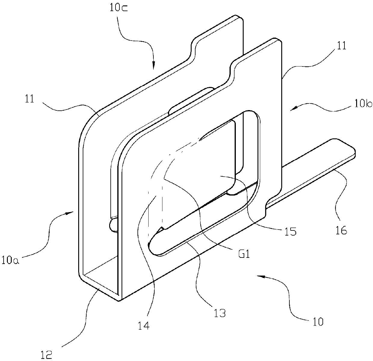
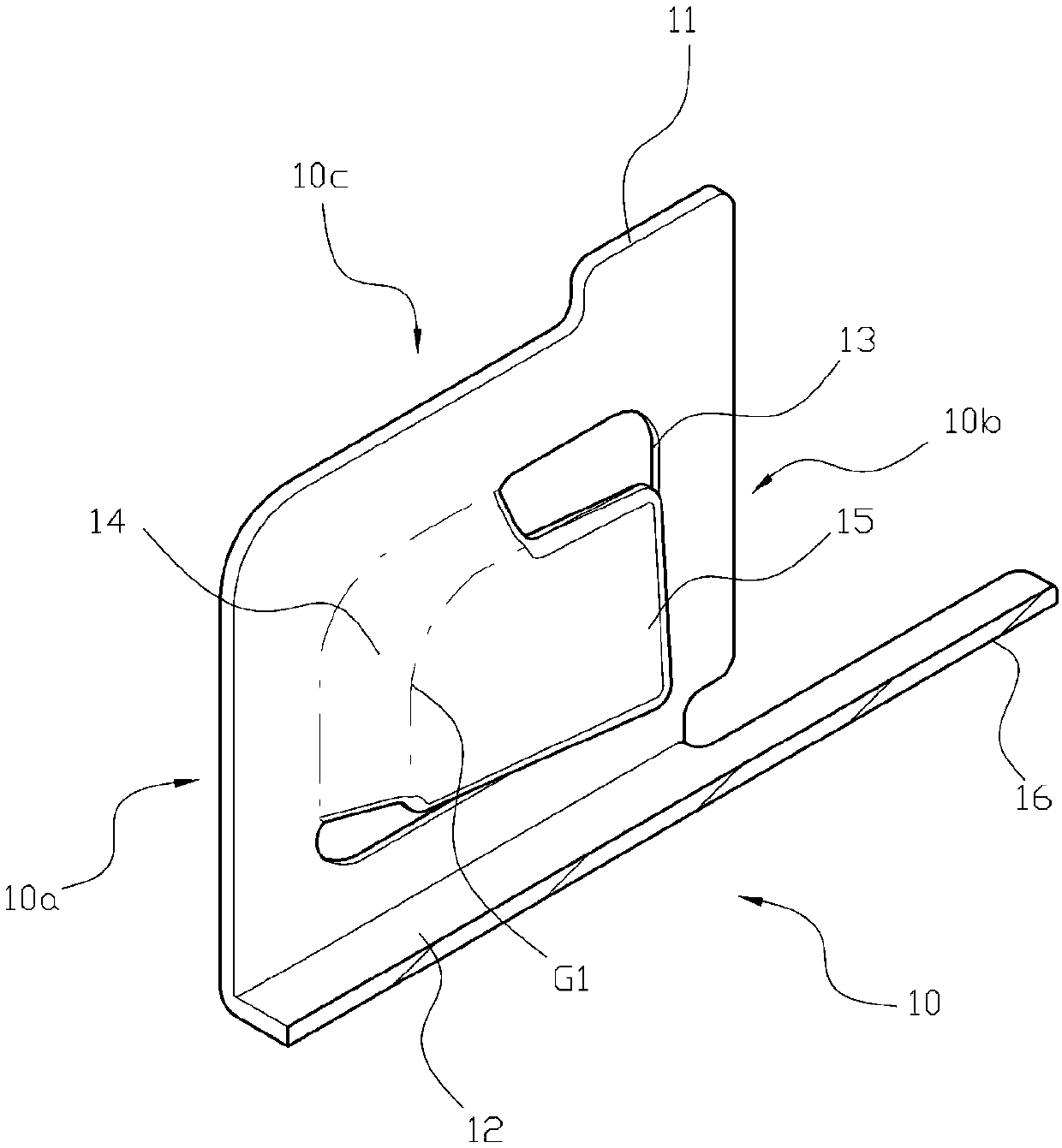
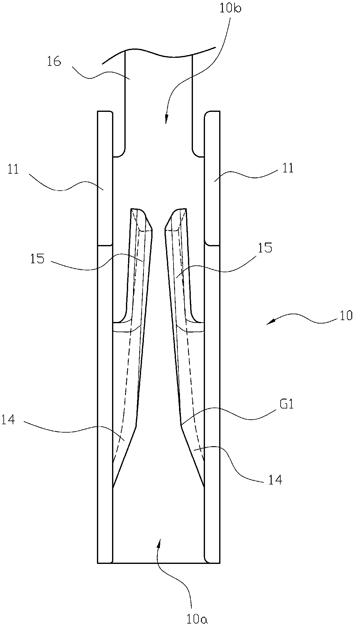
[0080] first please figure 1 Continuous to Figure 4 As shown, a terminal structure of a knife-type connector includes: at least one first terminal 10, the first terminal 10 is provided with two plates 11 in parallel, and the two plates 11 are arranged at intervals, and are formed by two A front insertion end 10a and an insertion end 10b are formed at intervals between the plates 11. A bottom plate 12 is connected between the two plates 11, and the first terminal 10 is provided with the bottom plate 12. An upper insertion end 10c is formed at the opposite end of the upper insertion end 10c, and a square opening 13 is provided on the two plates 11, and the square opening 13 of the plate 11 is integrally connected with the edge of the upper insertion end 10c adjacent to the front insertion end 10a. The arc portion 14 protruding inside forms the first clamping position G1 by the shortest distance between the two arc portions 14, and the two arc portions 14 are connected with fl...


PUM


Abstract

The invention relates to a terminal structure of a guillotine-type connector. The terminal structure comprises at least one first terminal, wherein the first terminals are each provided with two plates in parallel; a front insertion end, a plug tail end and an upper insertion end are formed between the two plates; a bottom plate is connected between the two plates; the plates are each integrally connected with an arc-shaped portion protruding inwardly at the position adjacent to the edges of the front insertion end and the upper insertion end; a first clamping position is formed at the shortest distance between the two arc-shaped portions; the arc-shaped portions are connected with clamping pieces that are flat and extend toward the plug tail end; the gap between the two clamping pieces diminishes gradually from the ends of the arc-shaped portions to the bottom plate and the plug tail end, so that the gap at the position, adjacent to the upper insertion end, between the two clamping pieces is relatively larger than that at the position, adjacent to the end of the bottom plate, between the two clamping pieces, thereby forming a surface-contact conductive state by elastic turning ofthe two clamping pieces.

Description

technical field [0001] The invention relates to a connector for a circuit, in particular to a terminal structure of a knife-type connector capable of improving the conductive contact effect of the terminal. Background technique [0002] A known connection structure of connector terminals, please refer to Figure 13 As shown, the connecting structure of the connector terminal includes a male terminal 60 and a female terminal 70, the female terminal 70 is formed with a fixing frame 71, and a front opening 72 and a rear opening 73 are formed at intervals by the fixing frame 71, the The female terminal 70 is bent inwardly from both sides of the fixing frame 71 to be provided with two arc bending pieces 74, and the arc bending pieces 74 extend from the front opening 72 end to the rear opening 73 end, and the male terminal 60 is formed by two arc bending pieces 74. Insert between the curved pieces 74, and use the curved piece 74 to squeeze the male terminal 60 to form a conductive...

Claims


Application Information

Patent Timeline
IPC IPC(8): H01R13/40H01R13/52
CPCH01R13/40H01R13/5202
Inventor 赖柄源赖启益张忠仁
Owner AVERTRONICS
Why Eureka
Try Eureka