Backlight lamp inclination surface glue dispenser for television production back plate
A backplane and backlight technology, which is applied to the device and coating of the surface coating liquid, can solve the problem of not being able to adjust the angle of the dispensing tube, and achieve the effect of saving costs
- Summary
- Abstract
- Description
- Claims
- Application Information
AI Technical Summary
Problems solved by technology
Method used
Image

Examples
Embodiment 1
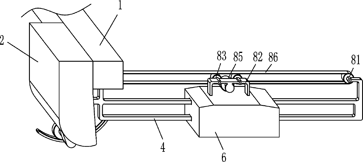
[0025] A kind of glue dispensing machine for the inclined plane of the backlight of the back panel of TV production, such as Figure 1-6 As shown, it includes a mounting frame 1, a mounting plate 2, a universal ball 3, a guide rod 4, a sliding block 5, a dispensing tube 6, a tilting mechanism 7 and a moving mechanism 8, and the left part of the upper outer side of the mounting frame 1 is fixed with a mounting plate 2. The lower part of the right side of the mounting plate 2 is rotatably equipped with a universal ball 3, the universal ball 3 is connected with a guide rod 4, and the sliding type on the guide rod 4 is provided with a sliding block 5, and the bottom of the sliding block 5 is assembled on the left side There is a rubber tube 6, and the guide rod 4 is provided with a moving mechanism 8 that can move the sliding block 5. The moving mechanism 8 is connected to the top of the sliding block 5, and the bottom of the mounting plate 2 is provided with a tilting mechanism 7 ...
Embodiment 2
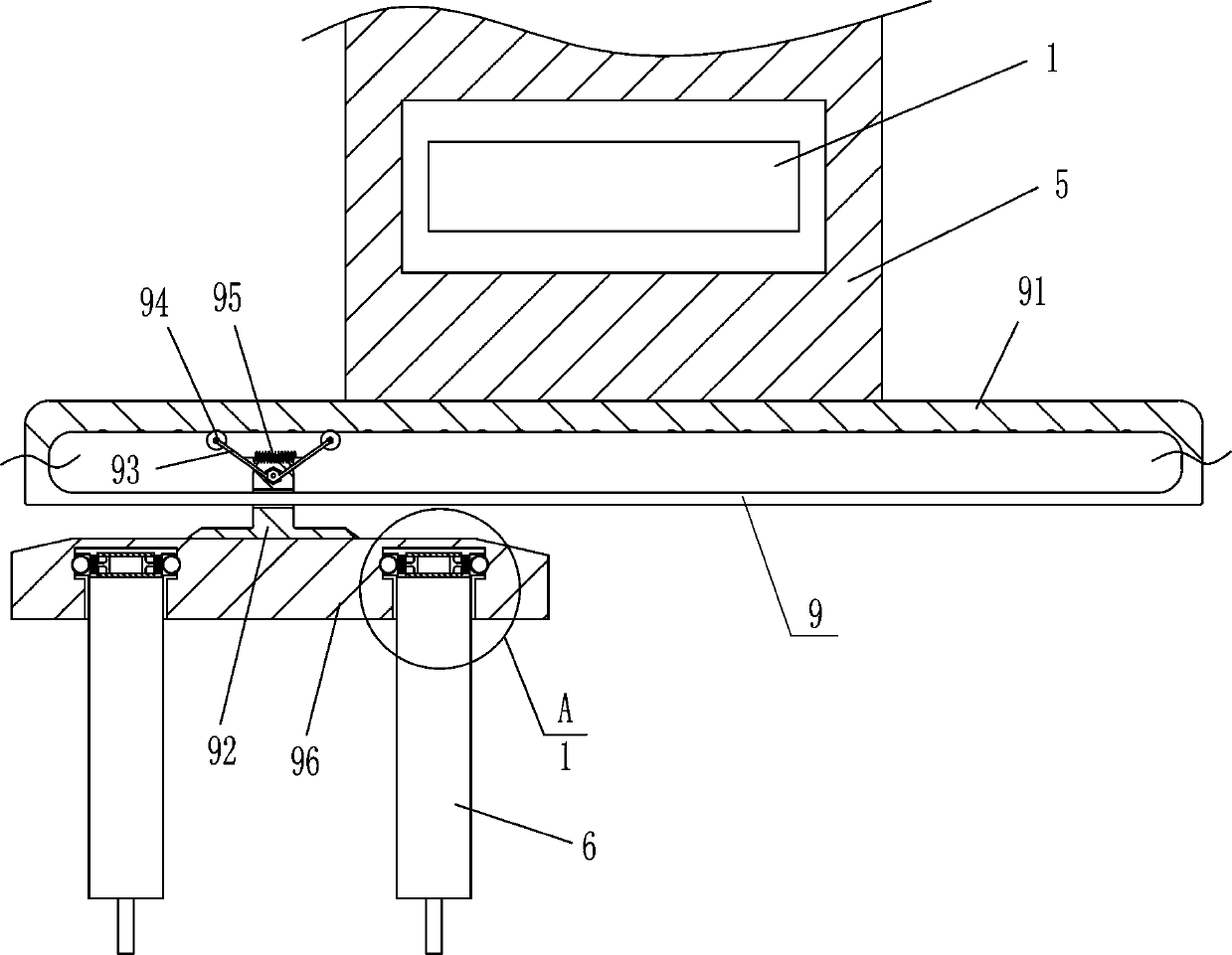
[0032] On the basis of embodiment 1, with reference to Figure 4 , Figure 5 and Figure 6, also includes an adjustment mechanism 9, the adjustment mechanism 9 includes a guide plate 91, a sliding plate 92, a swing lever 93, a clamping wheel 94, a tension spring 95, a horizontal plate 96 and a clamping mechanism 10, and the bottom of the sliding block 5 is fixed in the middle Be connected with guide plate 91, guide plate 91 bottom sliding type is provided with slide plate 92, and slide plate 92 top rotation type is connected with two swing rods 93, and swing rod 93 tail end rotation type is connected with clamping wheel 94, clamps Tightening wheel 94 contacts and cooperates with guide plate 91 inner top, is connected with tension spring 95 between two swing bars 93 inner surfaces, and cross plate 96 is installed on slide plate 92 bottoms, and cross plate 96 bottoms is provided with clamping mechanism 10, clamps The tightening mechanism 10 is assembled and connected with the ...
Embodiment 3
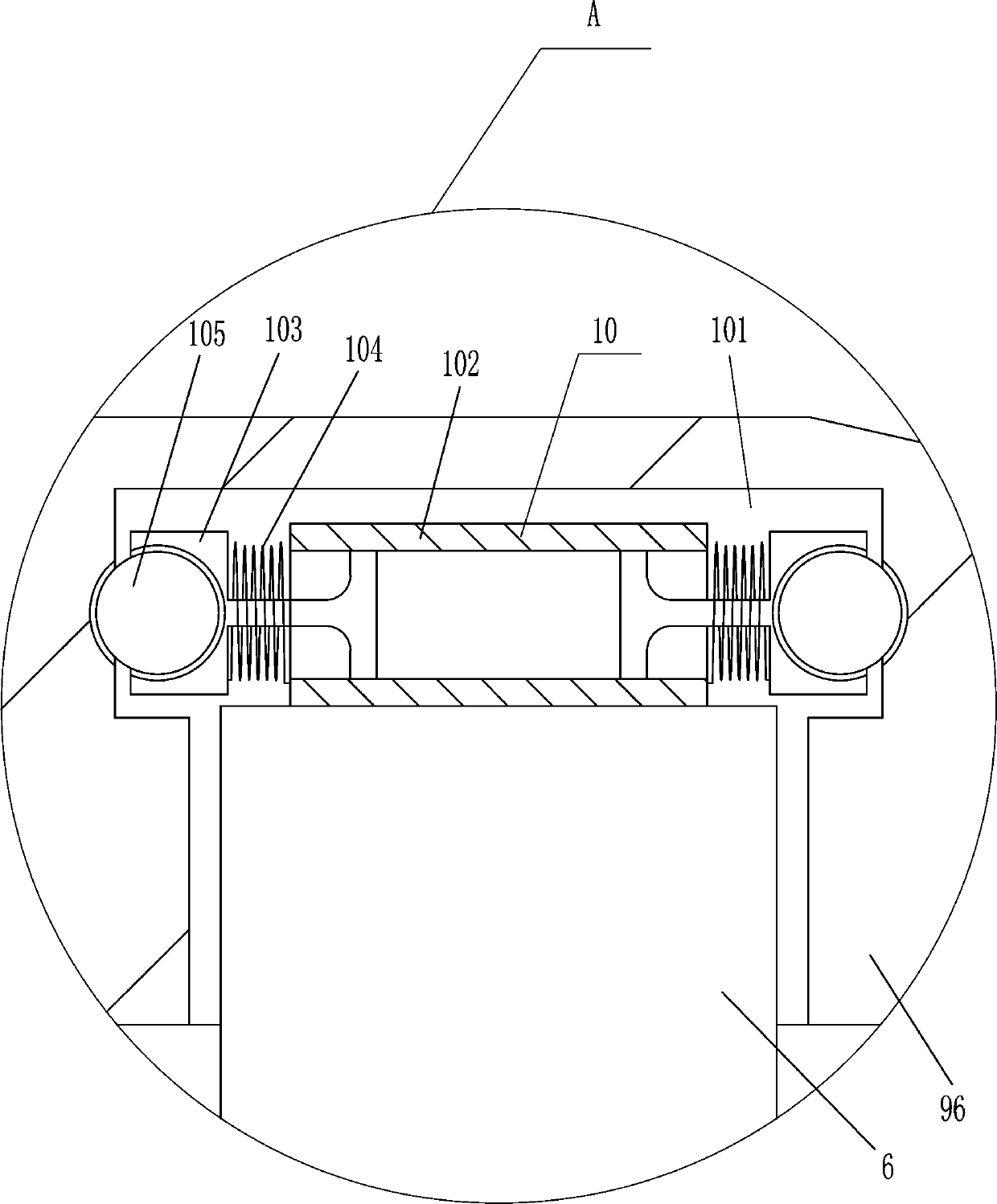
[0035] On the basis of embodiment 1 and embodiment 2, with reference to Figure 4 , Figure 5 and Figure 6 , the clamping mechanism 10 includes a hollow guide cylinder 102, a sliding seat 103, a compression spring 104 and a rolling ball 105. There are guide grooves 101 on the front and rear sides of the bottom of the horizontal plate 96, and a plurality of hollow holes are evenly spaced in the guide groove 101. Guide cylinder 102, the front and rear sides of hollow guide cylinder 102 inner wall are all slidingly provided with sliding seat 103, and the outer ends of front and rear sides sliding seat 103 are all rotatable to be provided with rolling ball 105, and rolling ball 105 cooperates with guide groove 101, front A compression spring 104 is wound between the inner front side of the side sliding seat 103 and the front end of the hollow guide cylinder 102, and a compression spring 104 is also wound between the inner rear surface of the rear sliding seat 103 and the rear en...
PUM
 Abstract
Description
Claims
Application Information