
Modular profile steel combination type machine vise

A combined and modularized technology, which is applied in the direction of metal processing machinery parts, clamping, supporting, etc., can solve the problems of taking up a lot of space, adjusting the friction force, and long cycle, so as to improve the utilization rate, reduce the friction force, reduce the The effect of processing fees

Inactive Publication Date: 2020-02-07
江苏一首机械科技有限公司
View PDF9 Cites 1 Cited by
  • Summary
  • Abstract
  • Description
  • Claims
  • Application Information

AI Technical Summary

Problems solved by technology

[0013] The purpose of the present invention is to solve many problems of the existing flat-nose pliers, such as large investment cost, long cycle, narrow application surface, large adjustment friction force, large space occupation, and easy to keep garbage in the sleeper rail and provide a modular steel Combined machine vise

Method used


Image

  • Modular profile steel combination type machine vise
  • Modular profile steel combination type machine vise
  • Modular profile steel combination type machine vise

Examples


Embodiment 1

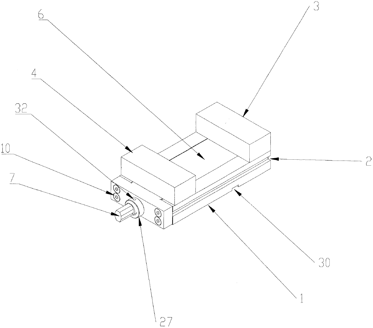
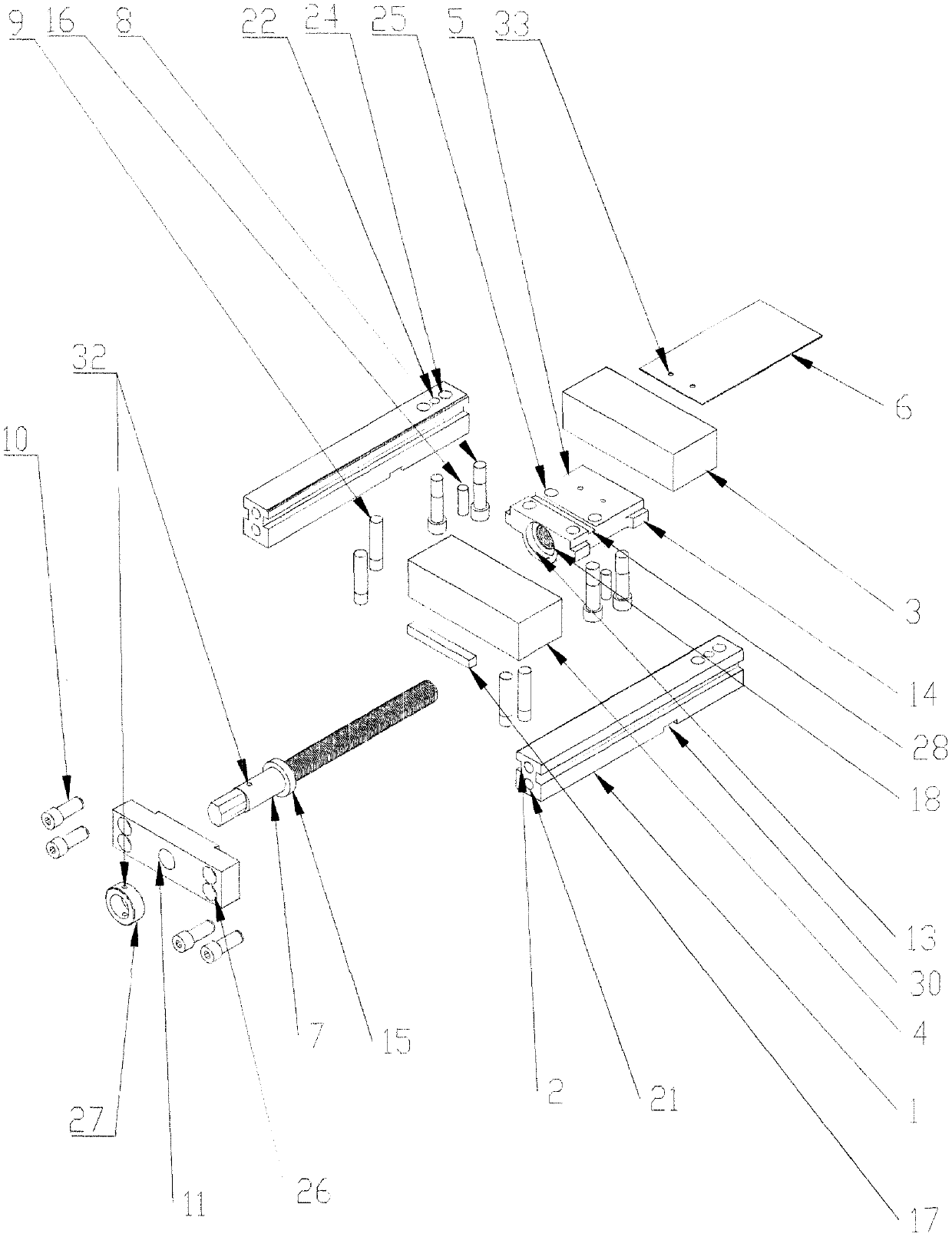
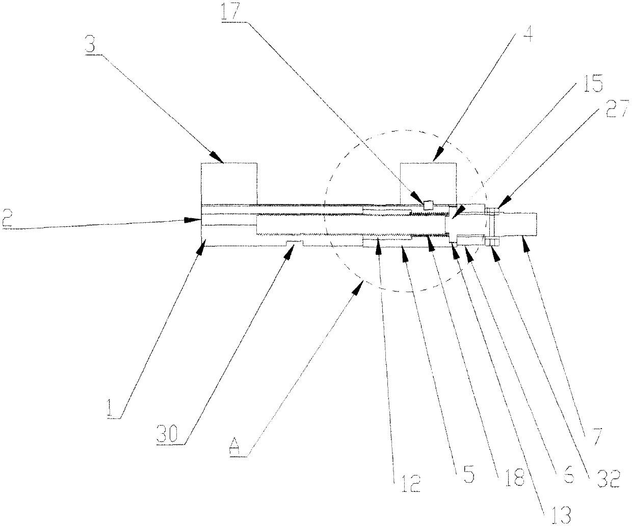
[0067] by Figure 1 to Figure 16 As shown in the overall three-dimensional view, internal cross-sectional view, individual component three-dimensional view, internal cross-sectional view and partial enlarged view of the present invention, a modular steel combined machine flat-nose pliers includes two elongated sleeper rails 1, the sleeper rail The cross section of 1 is an irregular I-shaped. The two sleeper rails 1 are installed horizontally at a certain distance between them. The first gap 2 in the middle part of the side is kept horizontal and corresponding. The two sleeper rails are provided with a second There are two gaps 30 (used to fix the sleeper rail 1 on the processing table), the top of the front ends of the two sleeper rails 1 is provided with a fixed jaw 3 fixedly connected; each sleeper rail 1 is connected to the fixed jaw The two first fixing holes 24 of the sleeper rail 1 penetrate from bottom to top (the number of the first fixing holes 24 is at least one, of co...

Embodiment 2

[0078] by Figure 17 to Figure 21 Another improved embodiment of the present invention is shown. On the basis of Example 1, the second notch 30 at the bottom is subtracted from the two sleeper rails 1, and a fixedly connected rotating chassis 36 is added at the bottom to rotate The main body of the chassis 36 is provided with an external hole 40 for connecting external equipment and or rotating parts; the place where the rotating chassis 36 intersects the two sleeper rails is provided with a bottom-up fourth fixing hole 39, in order to facilitate the two sleeper rails 1 to realize the positioning function, the middle of the two fourth fixing holes 39 is provided with a non-through third pin hole 37 (the first pin hole 22 and the second pin hole 23 in embodiment 1 can be eliminated or retained (Also) In this embodiment, the positions of the bottoms of the two sleeper rails 1 corresponding to the fourth fixing holes 39 and the first pin holes 37 of the rotating chassis 36 are pro...


PUM


Abstract

The invention relates to the technical field of light and convenient mechanically operated tools, in particular to a modular profile steel combination type machine vise. The modular profile steel combination type machine vise is provided in order to solve the problems that the existing vise is high in cost and regulating friction force is large. The machine vise comprises two sleeper tracks and afirst notch between the sleeper tracks, wherein one end of a fixed vise jaw is located through a pin and fixedly connected by a first bolt, and the horizontal position of the other end of the fixed vise jaw is fixedly connected with a baffle through a third bolt; a first axial hole is arranged in the middle of the baffle; a regulating nut is arranged between the two sleeper tracks, the two sides of the regulating nut are provided with first projections, a first screw hole is arranged in the middle of the regulating nut, the first screw hole and the first axial hole are located on the same axis, and a screw is arranged in the first screw hole through thread engagement connection; a second projection around the screw is arranged in the position close to the end part of the screw, and the diameter of the second projection is larger than the diameter of the first axial hole in the baffle; and a moving vise jaw located through a cross track and fixedly connected through a second bolt is arranged above the regulating nut.

Description

Technical field [0001] The invention relates to the field of sturdiness of portable power tools, and more specifically to a modular steel combined machine flat-nose pliers. Background technique [0002] Existing machine flat-nose pliers, no matter the material is cast iron or cast steel, the basic parts are all made of castings. It is mainly composed of a base, a fixed clamp body, and a movable clamp body with a force applying mechanism. [0003] The inventor discovered through decades of work experience that the objective shortcomings of the existing technology: [0004] 1. The main structural parts are made of castings, which can only be produced by opening a mold. The mold investment cost is large and the cycle is long. [0005] 2. When the main parameters of the product change, the mold needs to be re-opened for production, which is expensive and has a long cycle. [0006] 3. When the main structural parts of the clamp body are castings, the blank machining allowance is large, whi...

Claims


Application Information

Patent Timeline
Patent Type & Authority Applications(China)
IPC IPC(8): B23Q3/06B24B41/06
CPCB23Q3/066B24B41/06
Inventor 黄宁生乔甡曾卫民
Owner 江苏一首机械科技有限公司
Learn More