
Automatic pipe feeding device

An automatic feeding and feeding device technology, applied in the direction of pipe shearing device, shearing device, shearing machine equipment, etc., can solve the problems of increasing production cost, low feeding efficiency, and reducing work efficiency, so as to improve work efficiency, High degree of automation, the effect of improving work efficiency

Active Publication Date: 2020-02-07
CHANGZHOU TIANZHENG IND DEV CO LTD +1
View PDF7 Cites 6 Cited by
  • Summary
  • Abstract
  • Description
  • Claims
  • Application Information

AI Technical Summary

Problems solved by technology

Today's operation methods can be mainly divided into two types: manual loading and automatic loading. The traditional manual loading method requires full-time personnel to place the pipes from the pile to the processing equipment one by one with bare hands or using an electric hoist. During mass processing, The manual loading method leads to high labor intensity for operators, low feeding efficiency, and increases the risk of accidents; the automatic feeding method reduces the labor intensity of workers to a certain extent, but the existing automatic feeding usually uses flexible belts and coiled belts However, when this feeding method transfers pipes of different specifications from the stacking area to the material preparation area and the processing area, manual adjustments are still required, which greatly reduces work efficiency and increases production costs. extremely inconvenient

Method used


Image

  • Automatic pipe feeding device
  • Automatic pipe feeding device
  • Automatic pipe feeding device

Examples


Embodiment Construction

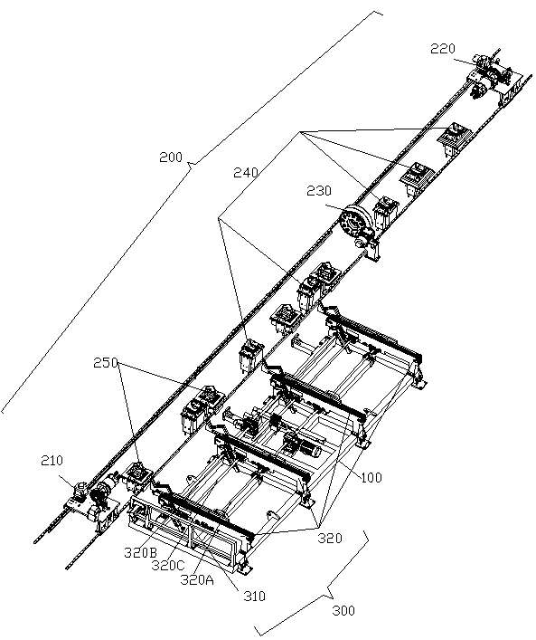
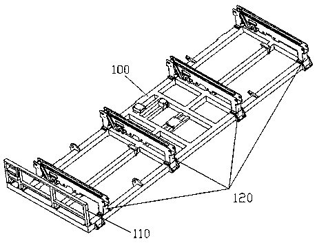
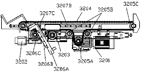
[0035] See Figure 1 to Figure 10, the present invention has a first frame 100, the first frame 100 is provided with a feeding station 300, and the side of the first frame 100 is provided with a feeder for receiving the pipe material on the feeding station 300 and feeding Work station 200, the feeding station 300 is provided with a plurality of feeding devices 320 for pipe material feeding in parallel, and the feeding device 320 includes a plurality of transmission brackets 120 parallel and fixedly arranged on the first frame 100 , a plurality of transmission chain belts 3204 for transporting pipes and driven by the first driving motor 3201, and a plurality of feeding racks 3207A driven by the second driving motor 3203 and used for transporting the pipes to the feeding station 200, One end of each feeding frame 3207A close to the feed station 200 is fixedly provided with a supporting frame for supporting the pipe on the transmission chain belt 3204, and each feeding frame 3207...


PUM


Abstract

The invention relates to an automatic pipe feeding device. The automatic pipe feeding device is provided with a first rack, wherein a feeding station is arranged on the first rack; a feeding station is arranged on the side edge of the first rack; a plurality of feeding devices are arranged on the feeding station in parallel; each feeding device comprises a plurality of transmission supports, a plurality of transmission chain belts and a plurality of feeding frames; the transmission supports are fixedly arranged on the first rack in parallel; the transmission chain belts are driven by a first driving motor to operate; the feeding frames are driven by a second driving motor to advance; a bearing frame is fixedly arranged at the end, close to the feeding station, of each feeding frame; each feeding frame is arranged on the first rack in a sliding mode through the second driving motor; each transmission chain belt is rotationally arranged on the corresponding transmission support through the first driving motor; a second rack is arranged on the feeding station; a first chuck and a second chuck are arranged on the first rack in a sliding mode; and a cutting electric chuck used for cutting pipes is fixedly arranged between the first chuck and the second chuck. The automatic pipe feeding device is ingenious in structure, and the production cost can be reduced while the working efficiency is effectively improved.

Description

technical field [0001] The invention relates to an automatic loading and feeding device for pipe materials. Background technique [0002] With the development of the national economy, pipes are widely used in machinery, construction and other fields. Different application fields have special requirements for the shape and length of pipes. Therefore, special equipment is required for deep processing of pipes. Today's operation methods can be mainly divided into two types: manual loading and automatic loading. The traditional manual loading method requires full-time personnel to place the pipes from the pile to the processing equipment one by one with bare hands or using an electric hoist. During mass processing, The manual loading method leads to high labor intensity for operators, low feeding efficiency, and increases the risk of accidents; the automatic feeding method reduces the labor intensity of workers to a certain extent, but the existing automatic feeding usually uses...

Claims


Application Information

Patent Timeline
IPC IPC(8): B23Q7/00B23D21/00
CPCB23D21/00B23Q7/003
Inventor 曾军河陈继良彭文斌吴佳张文波黄小林
Owner CHANGZHOU TIANZHENG IND DEV CO LTD
Learn More