Metal oil filling pipe for assembling plastic oil pipe head

A fuel oil pipe and oil pipe head technology, which is applied in the field of auto parts, can solve the problems of large human error, low standardization, and low elongation, and achieve the effect of reducing metal welding steps, no human error, and reducing overall weight

Pending Publication Date: 2020-02-07
戴胜汽车科技(苏州)有限公司
View PDF0 Cites 1 Cited by
  • Summary
  • Abstract
  • Description
  • Claims
  • Application Information

AI Technical Summary

Problems solved by technology

[0003] With the implementation of the National VI regulations "GB18352.6-2016", the requirements for vehicle weight and corrosion durability are getting higher and higher, and the existing low-carbon steel oil pipe head can no longer meet people's needs
Major OEMs have gradually begun to use stainless steel oil pipe heads to replace traditional low carbon steel oil pipe heads and weld them on the metal oil pipe main pipe 1 of the car. The corrosion resistance is greatly improved and it is stainless. However, it should be noted that the stainless steel material The elongation rate is much lower than that of low-carbon steel materials. The diameter reduction ratio of ordinary 1.0mm 304L stainless steel pipes can only reach 170%, while the diameter reduction ratio of ordinary 1.0mm low-carbon steel pipes is less than 210%. One-time flaring requires an additional stainless steel part for flaring transition. At the same time, another welding process is required, which increases the weight and production cost of the stainless steel oil filling pipe.
[0004] All in all, since the low-carbon steel and stainless steel oil pipe heads need to be connected to the metal fuel oil pipe main pipe 1 by welding, and multiple welding is required, the process is relatively complicated, and trained professionals are required to operate, which requires investment. High cost, large human error, low degree of standardization

Method used


Image

  • Metal oil filling pipe for assembling plastic oil pipe head
  • Metal oil filling pipe for assembling plastic oil pipe head
  • Metal oil filling pipe for assembling plastic oil pipe head

Examples


Embodiment 1

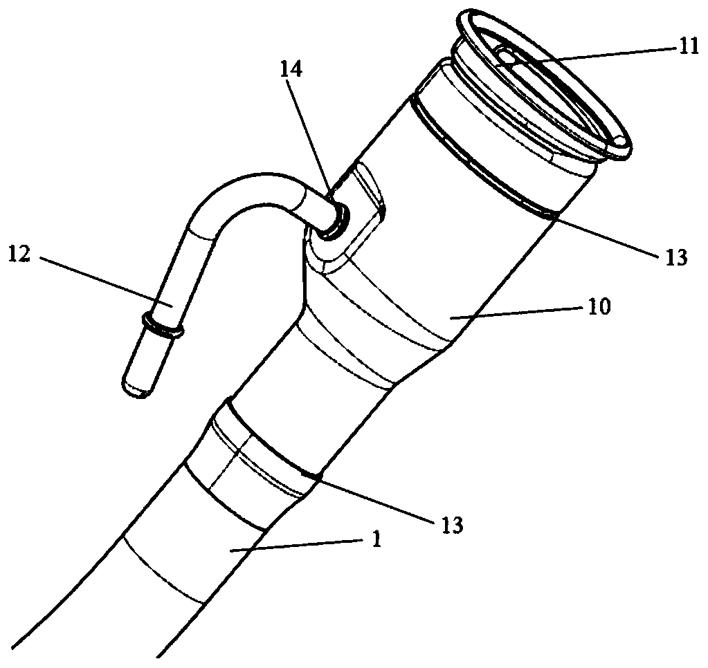
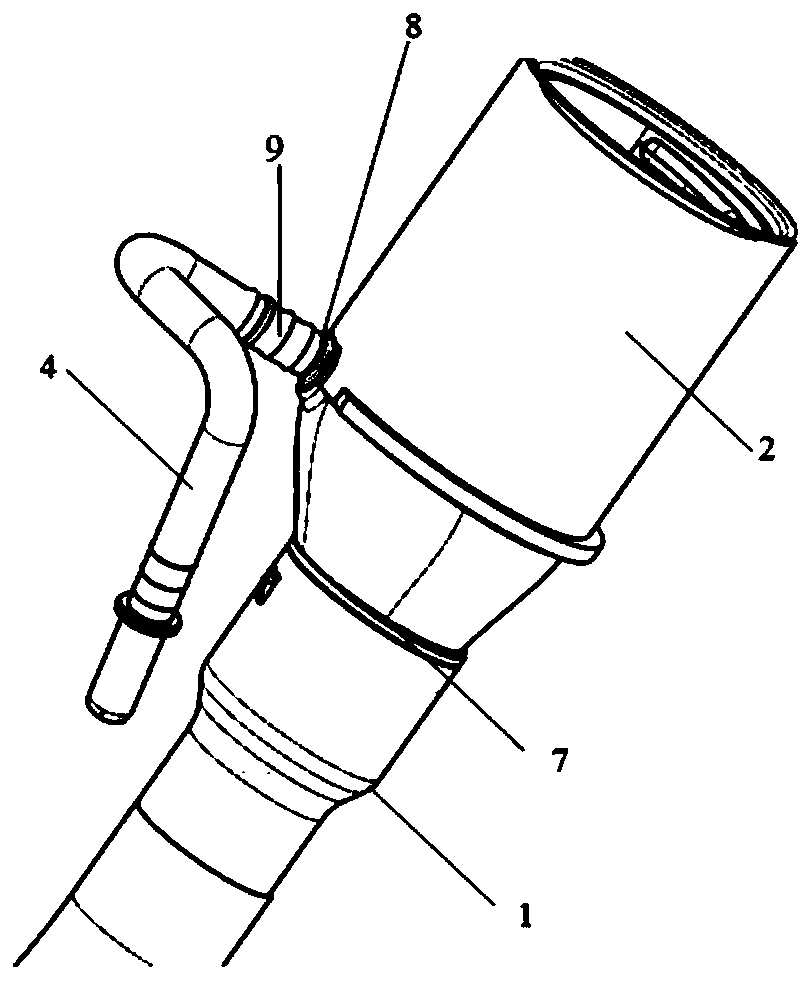
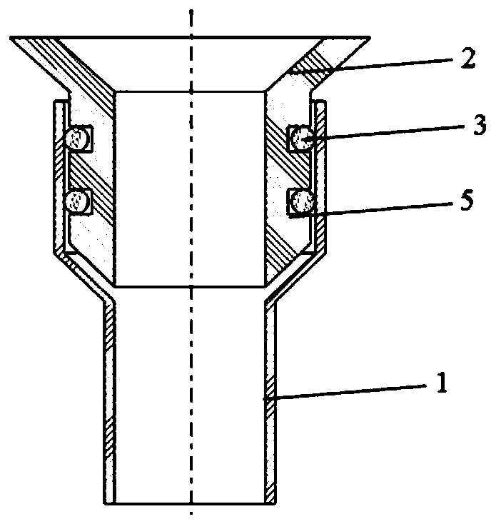
[0028] Such as Figure 2-3 with Figure 6-8 As shown, a metal filling pipe assembled with a plastic oil pipe head includes a main pipe 1 of a metal filling pipe and a part 2 of a plastic oil pipe head. The plastic oil pipe head part 2 is adapted to the main pipe 1 of a metal filling pipe. Together and between the two are sealed and connected by a seal 3, and one side of the plastic oil pipe head part 2 is assembled to connect to the air return pipe 4, and the function of the air return pipe 4 is to circulate fuel vapor during the refueling process of the car.

[0029] The plastic oil pipe head part 2 includes an upper section, a middle section and a lower section. The upper section and the lower section are respectively in a cylindrical structure and the two are connected together through the middle section. 2. The lower section is assembled at the first assembly place 7 with the main pipe 1 of the oil filling pipe through threaded connection, buckle, etc., and is detachably ...

Embodiment 2

[0034] Such as figure 2 , Figure 4 with Figure 6-8 As shown, a metal oil filling pipe assembled with a plastic oil pipe head includes a metal oil pipe head main body 1 and a plastic oil pipe head part 2. The plastic oil pipe head part 2 is adapted to the metal oil pipe main body 1, and the two are connected in an assembled manner. Together and between the two are sealed and connected by a seal 3, and one side of the plastic oil pipe head part 2 is assembled to connect the return air pipe 4, and the function of the air return pipe 4 is to circulate fuel vapor during the refueling process of the car.

[0035]The plastic oil pipe head part 2 includes an upper section, a middle section and a lower section. The upper section and the lower section are respectively in a cylindrical structure and the two are connected together through the middle section. 2. The lower section, at the first assembly point 7, is assembled with the main pipe 1 of the oil filling pipe through threaded...

Embodiment 3

[0039] Such as figure 2 with Figure 5-8 As shown, a metal oil filling pipe assembled with a plastic oil pipe head includes a metal oil pipe head main body 1 and a plastic oil pipe head part 2. The plastic oil pipe head part 2 is adapted to the metal oil pipe main body 1, and the two are connected in an assembled manner. Together and between the two are sealed and connected by a seal 3, and one side of the plastic oil pipe head part 2 is assembled to connect to the air return pipe 4, and the function of the air return pipe 4 is to circulate fuel vapor during the refueling process of the car.

[0040] The plastic oil pipe head part 2 includes an upper section, a middle section and a lower section. The upper section and the lower section are respectively in a cylindrical structure and the two are connected together through the middle section. 2. The lower section, at the first assembly point 7, is assembled with the fuel pipe main pipe 1 through threaded connection, buckle, et...


PUM


Abstract

The invention discloses a metal oil filling pipe for assembling a plastic oil pipe head. The metal oil filling pipe for assembling the plastic oil pipe head comprises a metal oil filling pipe main pipe and a plastic oil pipe head part; the metal oil filling pipe main pipe and the plastic oil pipe head part are connected together in an assembling mode and are connected in a sealing mode through sealing pieces; and one side of the plastic oil pipe head part is connected with an air return pipe in an assembling mode. According to the metal oil filling pipe for assembling the plastic oil pipe head, the plastic oil pipe head part and the metal oil filling pipe main pipe can be assembled and connected together by means of plugging, sleeving or buckling and the like, the plastic oil pipe head part and the metal oil filling pipe main pipe are detachably connected, the plastic oil pipe head part is used for replacing a traditional stainless steel or low carbon steel oil pipe head flaring or necking reducing part, an assembly connection mode is used for replacing a traditional welding connection mode, meanwhile, the sealing pieces such as sealing rings or sealing gaskets and the like are used at connection positions for sealing, the structure is simple, the efficiency is high, the sealing performance is good, the integral weight is greatly reduced, at least three metal welding steps arereduced, the production and investment costs are obviously reduced, artificial errors do not exist basically, and the standardization degree of parts is high.

Description

technical field [0001] The invention belongs to the technical field of auto parts, and in particular relates to a metal oil filling pipe assembled with a plastic oil pipe head. Background technique [0002] At present, most automobiles are fueled with gasoline or diesel oil and are equipped with special fuel tanks. For the convenience of fuel tank sealing and refueling, special metal filling pipes need to be set on the filling ports of the fuel tanks, and supporting oil pipe heads are arranged on the filling pipes. At present, most manufacturers use welding to connect the metal oil pipe head 10 of low carbon steel material to the main pipe 1 of the metal fuel oil pipe, and it is necessary to carry out multiple metal welding operations at three welding positions such as the first welding place 13 and the second welding place 14. welding, such as figure 1 shown. [0003] With the implementation of the National VI regulations "GB18352.6-2016", the requirements for vehicle wei...

Claims


Application Information

Patent Timeline
Patent Type & Authority Applications(China)
IPC IPC(8): B60K15/01
CPCB60K15/01
Inventor 刘鹏赵战胜
Owner 戴胜汽车科技(苏州)有限公司
Why Eureka
Try Eureka