
Movable uncoiling speed reducer for nonferrous metal working industry

A non-ferrous metal and gold processing technology, applied in transmission boxes, mechanical equipment, transmission parts, etc., can solve the problems of affecting the uncoiling quality, low uncoiling power, low uncoiling efficiency, etc., to take into account the overall structure of the reducer. Power limitation, taking into account the effect of unwinding power

Pending Publication Date: 2020-02-07
JIANGSU TAILONG MACHINERY GRP CO CO LTD
View PDF5 Cites 0 Cited by
  • Summary
  • Abstract
  • Description
  • Claims
  • Application Information

AI Technical Summary

Problems solved by technology

[0002] Uncoiler, as an important equipment of metal sheet and strip processing equipment unit, is one of the commonly used mechanical equipment in modern processing and manufacturing industry. When used in uncoiler, the traditional reducer is fixed, and the strip is uncoiled by pulling the plate and strip. Disadvantages of low unwinding efficiency
At the same time, since the motor and reducer are installed on the top of the reducer box, the strength of the top of the box needs to be strengthened. Limited by the size of the top of the box, the general motor power of the uncoiler is usually within 30kW, and the uncoiling power is low. The installation of auxiliary pressure rollers will increase the production cost virtually, and after uncoiling, it will assist uncoiling, and multiple uncoiling operations will affect the quality of uncoiling

Method used


Image

  • Movable uncoiling speed reducer for nonferrous metal working industry
  • Movable uncoiling speed reducer for nonferrous metal working industry
  • Movable uncoiling speed reducer for nonferrous metal working industry

Examples


Embodiment Construction

[0012] Further description will be made below in conjunction with the accompanying drawings.

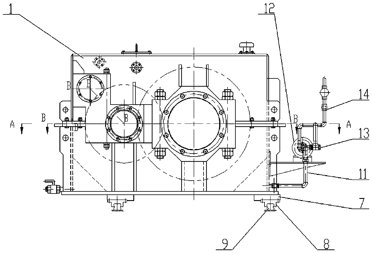
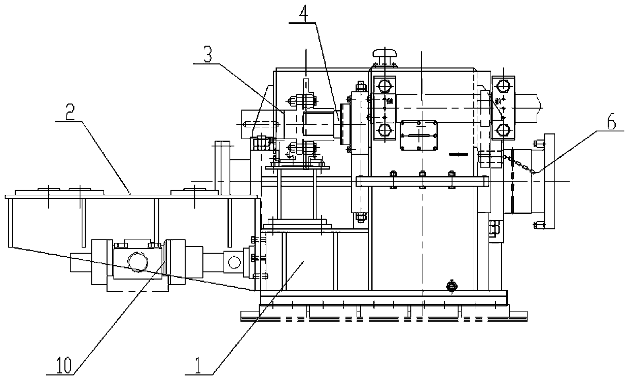
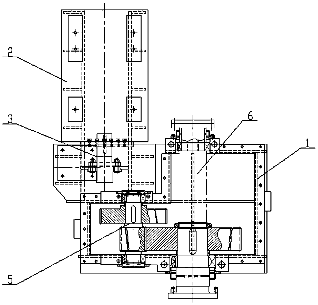
[0013] Figure 1-4 As shown, a movable decoiling reducer for the non-ferrous metal gold processing industry includes a box body 1, a motor bracket 2, a coupling 3, an input shaft 4, a multi-stage cylindrical gear transmission mechanism 5, an output shaft 6, and a foot seat 7 , Slide rail seat 8, track 9, hydraulic push rod cylinder 10, lubricating pipeline 11, oil pump 12, safety valve 13, lubricating piping 14. The input shaft 4 extends from the rear side of the box body 1, and the motor bracket 2 corresponding to the lower part of the output shaft is connected to the rear side of the box body 1. The motor bracket 2 is installed with the motor connected to the input shaft 4 through the coupling 3, and the front side of the output shaft 6 Stretch out the box corresponding to the uncoiling station, the left and right bases 7 of the box body 1 are connected with the slide rail seat 8 ...


PUM


Abstract

The invention relates to a movable uncoiling speed reducer for the nonferrous metal working industry. The movable uncoiling speed reducer comprises a box body, an input shaft, a multistage cylindricalgear transmission mechanism and an output shaft. The input shaft extends from the back side of the box body, the back side of the box body is connected with a motor support corresponding to the lowerpart of the output shaft, and the front side of the output shaft stretches out of a corresponding uncoiling station of the box body. The lower parts of left and right bottom foot bases of the box body are connected with sliding rail bases parallel to the output shaft and sliding on uncoiling station rails correspondingly. The box body on the back side of the output shaft is connected with a hydraulic push rod cylinder to push the sliding rail bases to slide on the uncoiling station rails. The box body is further provided with a lubrication pipeline, a lower opening of the lubrication pipelineis connected with the lower part of the box body, the lubrication pipeline is divided into two branches, one branch is connected with an oil pump, the other branch is connected with a safety valve, and the two branches are collected and connected with the upper part of the box body through a lubrication distribution pipe for oil return lubrication. The movable uncoiling speed reducer is compact in structure and can effectively take motor uncoiling power and speed reducer overall structure arrangement into account.

Description

technical field [0001] The invention relates to a speed reducer, in particular to a movable decoiling speed reducer for the non-ferrous metal gold processing industry. Background technique [0002] Uncoiler, as an important equipment of metal plate and strip processing equipment unit, is one of the commonly used mechanical equipment in modern processing and manufacturing industry. When used in uncoiler, the traditional reducer is fixed, and the strip is uncoiled by pulling the plate and strip. The disadvantage of low unwinding efficiency. At the same time, since the motor and reducer are installed on the top of the reducer box, the strength of the top of the box needs to be strengthened. Limited by the size of the top of the box, the general motor power of the uncoiler is usually within 30kW, and the uncoiling power is low. The installation of auxiliary pressure rollers will increase the production cost virtually, and after uncoiling, it will assist uncoiling, and multiple ...

Claims


Application Information

Patent Timeline
Patent Type & Authority Applications(China)
IPC IPC(8): F16H57/02F16H57/023F16H57/04
CPCF16H57/02F16H57/023F16H57/0423F16H57/0434F16H2057/02034F16H2057/02069
Inventor 康宝刚殷爱国殷庆凤陆晓妹周小飞张梅红殷桂虎蒋军翁燕蔡云龙张介禄
Owner JIANGSU TAILONG MACHINERY GRP CO CO LTD
Learn More