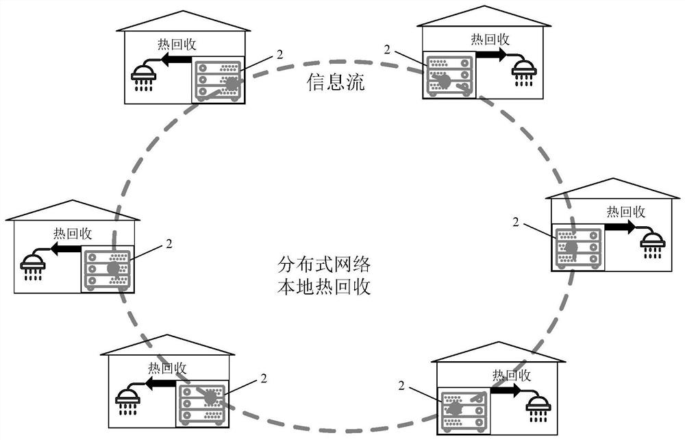
Distributed data center heat recovery heating system
A technology of distributed data and heating system, applied in the intersection of HVAC and information network, can solve the problems of difficult heat dissipation, large area of centralized data center, high construction and operation and maintenance costs, high heat dissipation efficiency, controllable The effect of running costs, ease of maintenance and replacement
- Summary
- Abstract
- Description
- Claims
- Application Information
AI Technical Summary
Problems solved by technology
Method used
Image
Examples
Embodiment 1
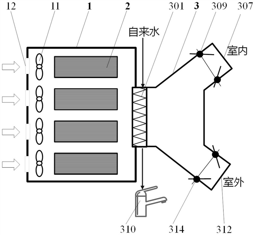
[0039] The distributed data center heat recovery heating system provided in this embodiment, such as figure 2 As shown, it includes: a cabinet 1, a server 2, and a heat recovery and heating module 3. The server 2 is discretely installed in the cabinet 1 , and the cabinet 1 is connected to the heat recovery and heating module 3 , and a cooling fan 11 and an air vent 12 are also arranged in the cabinet 1 .
[0040] The heat recovery heating module 3 includes a heat exchanger 301 , an indoor air outlet pipe 307 , an indoor air outlet pipe damper 309 , an outdoor air outlet pipe 312 , and an outdoor air outlet pipe damper 314 .
[0041] One side of the heat exchanger 301 is embedded in the cabinet 1, and the other side is connected to the indoor air outlet pipe 307 and the outdoor air outlet pipe 312 respectively through a structure similar to a three-way pipe. The indoor air outlet pipe 307 is installed indoors and connected to the indoor air outlet pipe. The air outlet pipe damp...
Embodiment 2
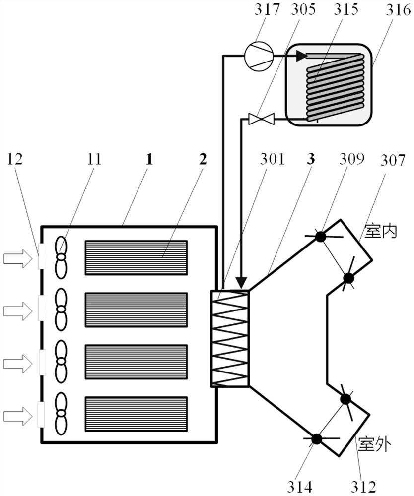
[0045] Embodiment 2 On the basis of Embodiment 1, a water-cooled coil condenser 315 and a heat storage tank 316 are added. The input end of the water-cooled coil condenser 315 is connected to the refrigerant outlet of the heat exchanger 301 through a compressor 317 , and the output end of the water-cooled coil condenser 315 is connected to the refrigerant inlet and outlet of the heat exchanger 301 through a throttling device 305 . The water-cooled coil condenser 315 is arranged inside the heat storage tank 316, such as image 3 shown.
[0046] When the compressor 317 and the throttling device 305 are turned on, and the air valve 309 of the indoor air outlet pipe and the indoor air outlet pipe 307 are closed, based on the principle of forced convection, the heat recovery heating module 3 operates in the heat pump circulation mode to obtain a higher temperature The domestic hot water is stored in the hot water storage tank 316 .
[0047] The working method of this embodiment i...
Embodiment 3
[0053] This example Figure 5 As shown, it includes a cabinet 1, a server 2, and a heat recovery and heating module 3. Wherein, the heat recovery heating module 3 includes an evaporator 302, a compressor 317, a heat dissipation branch valve 308, an air-cooled condenser 311, a heat storage branch valve 313, a water-cooled coil condenser 315, a heat storage tank 316, a flow device 305 . The heat dissipation branch valve 308 is connected with the air-cooled condenser 311 to form a heat dissipation branch; the heat storage branch valve 313, the water-cooled coil condenser 315, and the hot water storage tank 316 form a heat storage branch, and the heat storage branch valve 313 is connected to the water-cooled The coil condenser 315 and the cold coil condenser 315 are arranged inside the heat storage tank 316 .
[0054] The evaporator 302 is connected in parallel with the heat dissipation branch and the heat storage branch respectively, and the input ends of the evaporator 302 and...
PUM
 Abstract
Description
Claims
Application Information
 - R&D
- Intellectual Property
- Life Sciences
- Materials
- Tech Scout
- Unparalleled Data Quality
- Higher Quality Content
- 60% Fewer Hallucinations
Browse by: Latest US Patents, China's latest patents, Technical Efficacy Thesaurus, Application Domain, Technology Topic, Popular Technical Reports.
© 2025 PatSnap. All rights reserved.Legal|Privacy policy|Modern Slavery Act Transparency Statement|Sitemap|About US| Contact US: help@patsnap.com


