
Display panel and display device

A display panel and display area technology, which is applied to diodes, semiconductor devices, electrical components, etc., can solve the problems of inability to display pictures, increased screen ratio of display devices, and inability to display pictures at slot positions, so as to improve viewing effects and improve effect of brightness

Active Publication Date: 2022-04-05
KUNSHAN GO VISIONOX OPTO ELECTRONICS CO LTD
View PDF18 Cites 0 Cited by
  • Summary
  • Abstract
  • Description
  • Claims
  • Application Information

AI Technical Summary

Problems solved by technology

[0003] At present, display devices such as mobile phones and tablet computers need to be equipped with various components such as front cameras and earpiece distance sensors. It is necessary to slot the front of the display device for the above components, and the slots cannot display images. For example, the current The notch area or the opening of the screen, the notch area and the opening area cannot display the picture, which seriously limits the increase of the screen ratio in the display device, making it impossible to realize the full screen

Method used


Image

  • Display panel and display device
  • Display panel and display device
  • Display panel and display device

Examples


Embodiment Construction

[0060] In order to make the above objects, features and advantages of the present invention more comprehensible, specific embodiments of the present invention will be described in detail below in conjunction with the accompanying drawings.

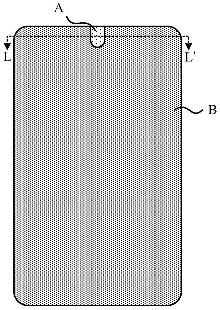
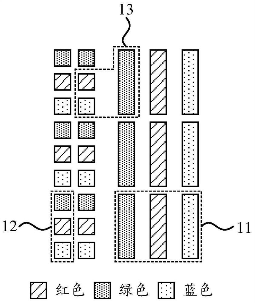
[0061] figure 1 It is a schematic structure diagram of a display panel shown according to an embodiment of the present disclosure. figure 2 yes figure 1 A schematic cross-sectional view of the display panel along LL' is shown.

[0062] Such as figure 1 and figure 2 As shown, the display panel includes a first display area A and a second display area B, wherein the light transmittance of the first display area is greater than the light transmittance of the second display area, further, by setting the first The structure of the display area makes the first display area tend to be transparent when no image is displayed.

[0063] Under the first display area A, an image acquisition device, a distance sensor, an ambient light sensor, etc...


PUM


Abstract

The present disclosure provides a display panel, including a first display area and a second display area, the first display area includes first sub-pixels of n colors, and the second display area includes second sub-pixels of n colors; wherein, in In the first display area, the first sub-pixels of the first group of colors adjacent to the second display area, and the second sub-pixels of the second group of colors in the second display area form a transition pixel unit. According to an embodiment of the present disclosure, since in the first display area, the first sub-pixels of the first group of colors adjacent to the second display area and the second sub-pixels of the second group of colors in the second display area form a transition For the pixel unit, when the transition pixel unit is controlled to emit light, the first sub-pixel and the second sub-pixel in the transition pixel unit can emit light together, thereby increasing the brightness at the boundary line between the first display area and the second display area, so that the boundary line The black lines formed are not easily seen.

Description

technical field [0001] The present disclosure relates to the field of display technology, and in particular, to a display panel and a display device. Background technique [0002] With the development of display devices, users' requirements for viewing effects are also increasing. An important factor that affects the viewing effect in a display device is the screen-to-body ratio, that is, the percentage of the effective display area on the front of the display device. The higher the screen-to-body ratio, the better the user's viewing effect. screen, which means that the screen-to-body ratio approaches 100%. [0003] At present, display devices such as mobile phones and tablet computers need to be equipped with various components such as front cameras and earpiece distance sensors. It is necessary to slot the front of the display device for the above components, and the slots cannot display images. For example, the current The notch area and the hole area cannot display the...

Claims


Application Information

Patent Timeline
Patent Type & Authority Patents(China)
IPC IPC(8): H01L27/32
CPCH10K59/60H10K59/65H10K59/121
Inventor 刘明星许立雄韩冰赵莹甘帅燕
Owner KUNSHAN GO VISIONOX OPTO ELECTRONICS CO LTD
Learn More