Display device, display panel and manufacturing method thereof

A technology of display panel and manufacturing method, which is applied in the technical field of display, can solve the problems of different thicknesses of flat layers, etc., and achieve the effect of reducing uneven thickness

Active Publication Date: 2020-02-07
BOE TECH GRP CO LTD +1
View PDF4 Cites 4 Cited by
  • Summary
  • Abstract
  • Description
  • Claims
  • Application Information

AI Technical Summary

Problems solved by technology

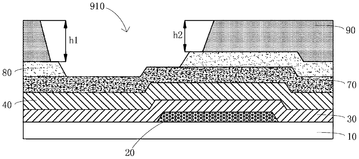
However, at the location of the auxiliary cathode hole, which is located close to the top of the gate trace, resulting in a different thickness of the flat layer inside the hole

Method used


Image

  • Display device, display panel and manufacturing method thereof
  • Display device, display panel and manufacturing method thereof
  • Display device, display panel and manufacturing method thereof

Examples


Embodiment Construction

[0045] Example embodiments will now be described more fully with reference to the accompanying drawings. Example embodiments, however, can be embodied in various forms and should not be construed as limited to the examples set forth herein; rather, these embodiments are provided so that this disclosure will be thorough and complete, and will fully convey the concept of example embodiments to those skilled in the art. The described features, structures, or characteristics may be combined in any suitable manner in one or more embodiments. In the following description, numerous specific details are provided in order to give a thorough understanding of the embodiments of the present disclosure. However, those skilled in the art will appreciate that the technical solutions of the present disclosure may be practiced without one or more of the specific details being omitted, or other methods, steps, etc. may be adopted. In other instances, well-known solutions have not been shown o...


PUM

PropertyMeasurementUnit
thicknessaaaaaaaaaa
thicknessaaaaaaaaaa
thicknessaaaaaaaaaa

Abstract

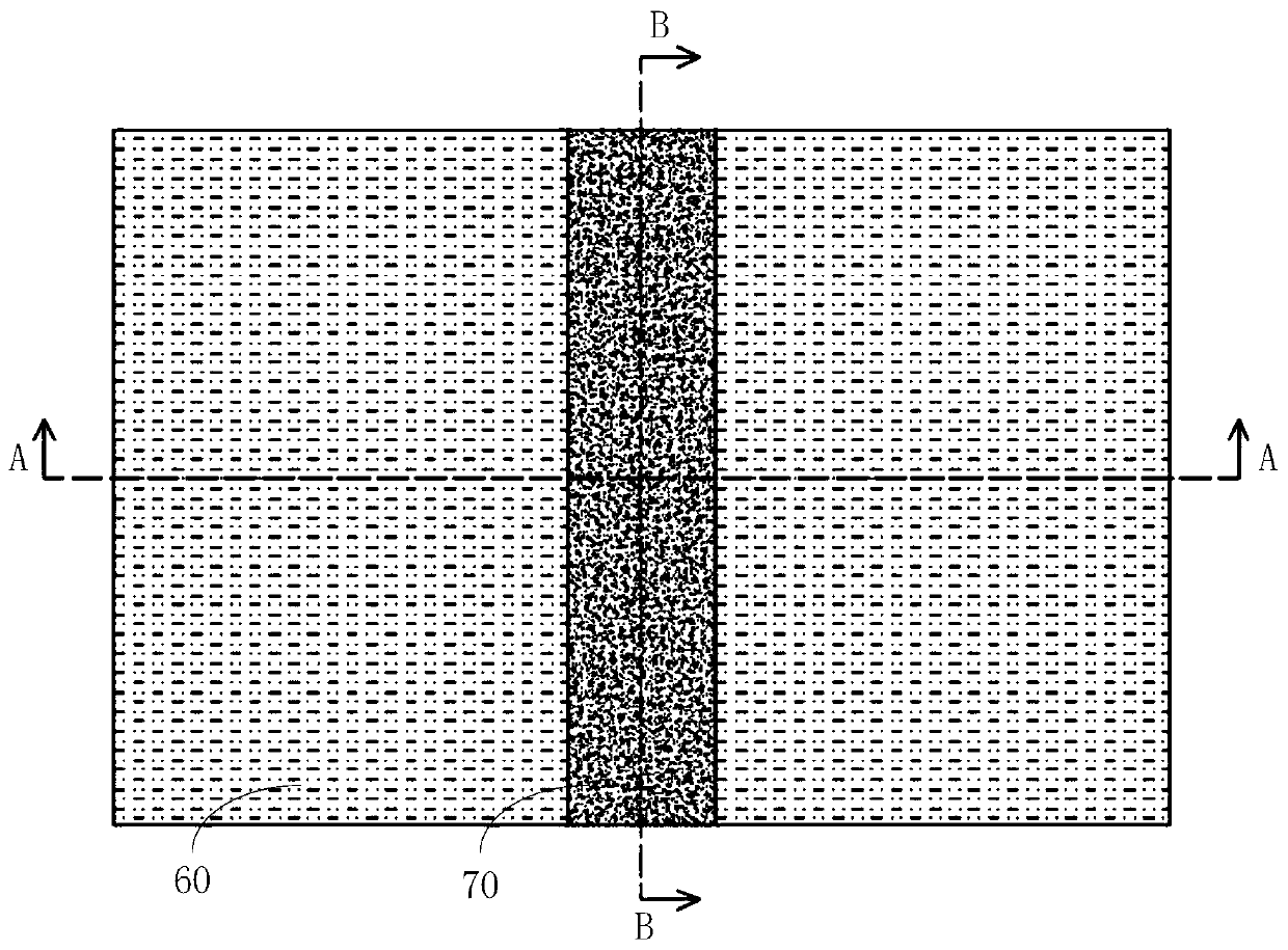
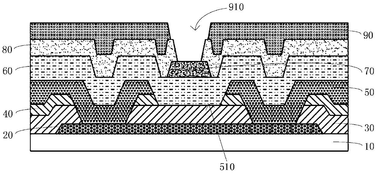
The invention relates to a display device, a display panel and a manufacturing method thereof. The display panel comprises a substrate, a conducting layer, a grid insulating layer, a grid layer, an interlayer dielectric layer and a wiring layer. The conducting layer is arranged on one side of the substrate; the grid insulating layer is arranged on one side, away from the substrate, of the conducting layer; the grid layer is arranged on one side, away from the substrate, of the grid insulating layer; and the thickness of the grid layer is greater than that of the conducting layer. The grid layer comprises a plurality of gate lines. The gate lines form grooves which extend towards the substrate and cut off the gate lines; the grooves are opposite to the conducting layer; and the broken gatelines at the two sides of the grooves penetrate through the grid insulating layer and are connected with the conducting layer. The interlayer dielectric layer is arranged on one side, away from the substrate, of the grid layer, and covers the conducting layer and fills the grooves; the wiring layer is arranged on the side, away from the substrate, of the interlayer dielectric layer; the wiring layer comprises a plurality of auxiliary electrode wires; and the orthographic projections of the auxiliary electrode wires on the grid layer intersect with the gate wires in the grooves, and the orthographic projections of the intersection parts on the grid layer are completely located in the grooves.

Description

technical field [0001] The present disclosure relates to the technical field of display technology, and in particular, to a display panel, a manufacturing method thereof, and a display device. Background technique [0002] Organic Light Emitting Diode (OLED) display panel has thin, light, wide viewing angle, active light emission, continuously adjustable light color, fast response speed, low energy consumption, simple production process, high luminous efficiency and flexible display, etc. Advantages, it has been listed as a promising next-generation display technology, and is widely used in various electronic products. [0003] At present, OLED display panels are divided into top emission and bottom emission structures. In the top emission structure, the light emitted by the OLED display panel is transmitted from the direction of the cathode, so the cathode of the top emission OLED panel needs to use a transparent conductive material, but due to the OLED cathode The materia...

Claims


Application Information

Patent Timeline
Patent Type & Authority Applications(China)
IPC IPC(8): H01L27/32H01L51/52H01L51/56
CPCH10K59/1315H10K59/131H10K50/814H10K50/824H10K59/1201H10K71/00H01L27/124H01L27/1248H10K59/124H10K59/126H10K2102/341H10K2102/351H10K50/844
Inventor 胡迎宾赵策王明丁远奎宋威闫梁臣
Owner BOE TECH GRP CO LTD
Why Eureka
Try Eureka