Separator assembly and battery module

A technology for isolation boards and components, which is applied to battery pack parts, secondary batteries, circuits, etc., and can solve problems such as large volume, cost reduction, and complex overall structure of isolation board components

Active Publication Date: 2020-02-07
CONTEMPORARY AMPEREX TECH CO
View PDF6 Cites 9 Cited by
  • Summary
  • Abstract
  • Description
  • Claims
  • Application Information

AI Technical Summary

Problems solved by technology

However, the traditional isolation plate components generally have the following problems: (1) most of the isolation plates cannot provide a fixing force for the electrical connector in the height direction, resulting in the risk of the electrical connector falling off under vibration conditions; (2) Although some isolation boards can provide fixing force for the electrical connectors in the height direction, it is necessary to place the electrical connectors on the isolation board from top to bottom. In order to facilitate assembly, the fixed structure on the isolation board will reserve a certain amount of space for assembly. space, resulting in low reliability of fixing between the isolation board and the electrical connection sheet; (3) The overall structure of the isolation board assembly is complex and bulky, which is not conducive to cost reduction

Method used


Image

  • Separator assembly and battery module
  • Separator assembly and battery module
  • Separator assembly and battery module

Examples


Embodiment Construction

[0043] The separator plate assembly and the battery module according to the present invention will be described in detail below with reference to the accompanying drawings.

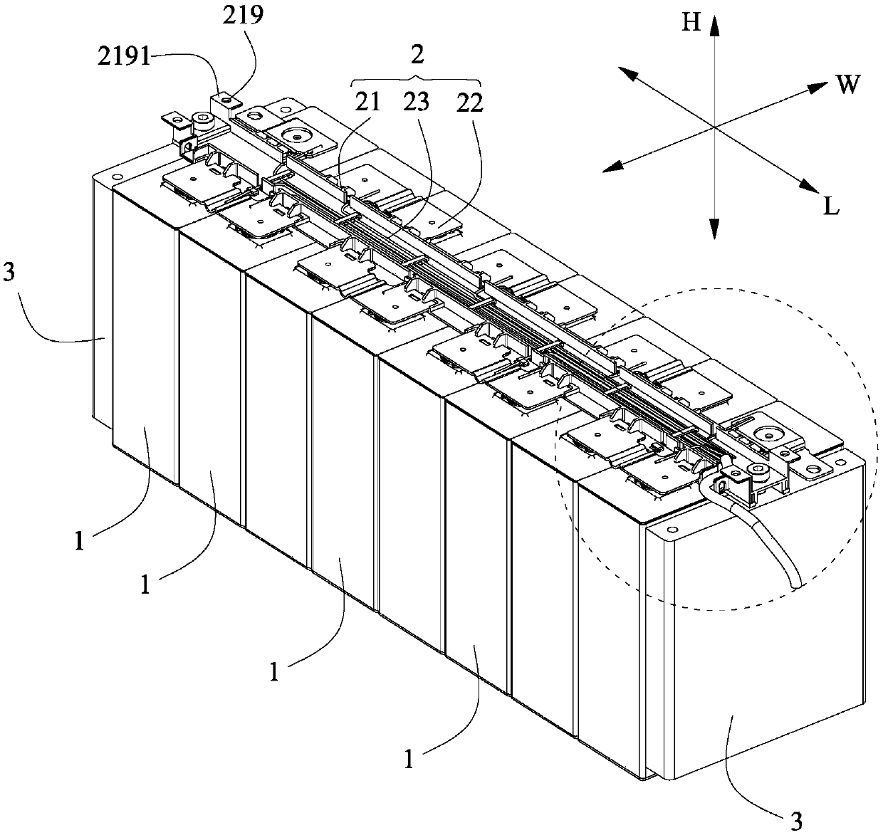
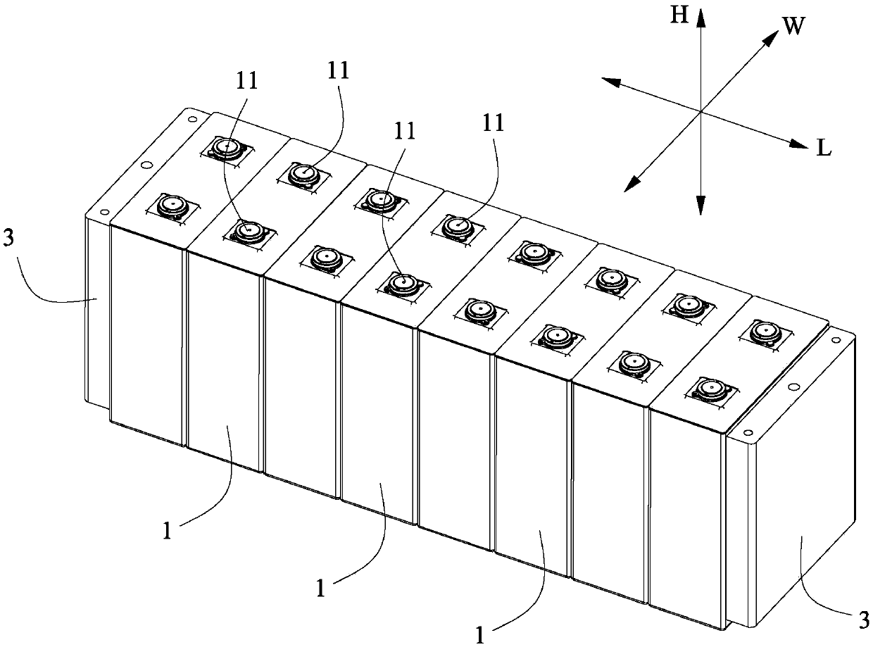
[0044] refer to Figure 1 to Figure 3 , The battery module according to the present invention includes a plurality of batteries 1, a separator assembly 2, two end plates 3 and an upper cover (not shown).

[0045] A plurality of batteries 1 are arranged side by side along the length direction L, and each battery 1 has two poles 11 arranged at intervals along the width direction W.

[0046] The two end plates 3 are respectively located at both ends of the length direction L of the plurality of batteries 1 . The two end plates 3 are used to clamp the plurality of batteries 1 in the length direction L. As shown in FIG.

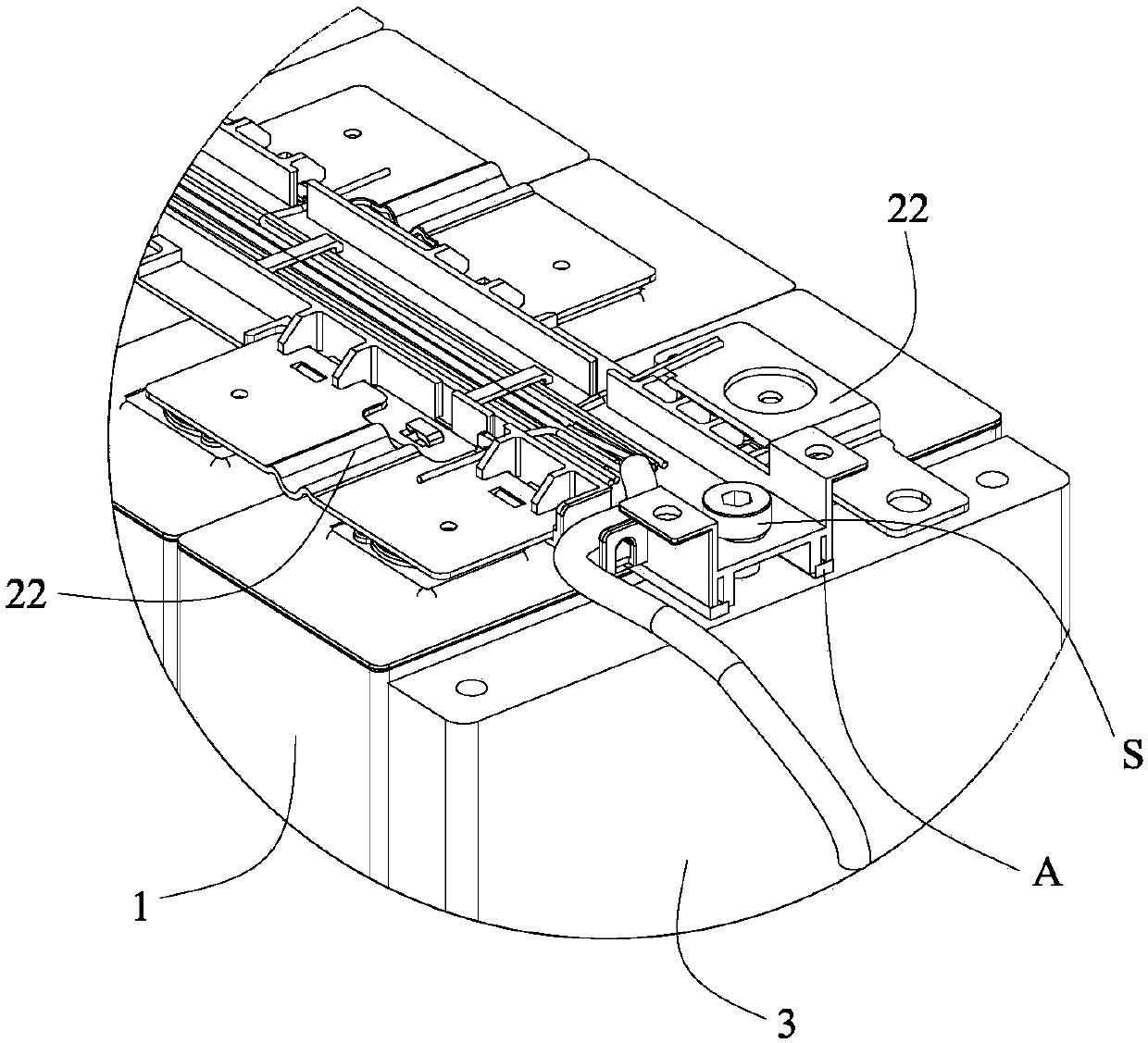
[0047] refer to figure 1 , the isolation plate assembly 2 includes an isolation plate 21 , a plurality of electrical connecting pieces 22 and a plurality of sampling wire harnesses 23 . W...


PUM


Abstract

The present invention provides a separator assembly and a battery module. The separator assembly includes a separator and a plurality of electrical connecting sheets. The separator is provided with aplurality of supporting parts and a plurality of first limiting parts. There is a space between each first limiting part and a corresponding supporting part along the height direction. Each electricalconnecting sheet has a first end and a second end which is arranged opposite to the first end in the width direction. The first end of each electrical connecting sheet is accommodated in the corresponding space and is clamped and fixed by the corresponding first limiting part and supporting part. The second end extends to the outside of the supporting part in the width direction. In the process of assembly, the first end of each electrical connecting sheet can be directly inserted into the corresponding space from one side of the separator in the width direction. The assembly method is simpleand fast, and the assembly efficiency is improved. Since the first end of each electrical connecting sheet is supported above the corresponding supporting part and the second end extends to the outside of the supporting part in the width direction, the volume of the separator is greatly reduced.

Description

technical field [0001] The invention relates to the technical field of batteries, in particular to an isolation plate assembly and a battery module. Background technique [0002] The isolation plate assembly generally includes an isolation plate and an electrical connection piece, and the function of the isolation plate is to limit the position of the electrical connection piece. However, the traditional isolation plate components generally have the following problems: (1) most of the isolation plates cannot provide a fixing force for the electrical connector in the height direction, resulting in the risk of the electrical connector falling off under vibration conditions; (2) Although some isolation boards can provide fixing force for the electrical connectors in the height direction, it is necessary to place the electrical connectors on the isolation board from top to bottom. In order to facilitate assembly, the fixing structure on the isolation board will reserve a certain...

Claims


Application Information

Patent Timeline
Patent Type & Authority Applications(China)
IPC IPC(8): H01M2/20H01M50/209H01M50/50H01M50/502
CPCH01M50/50H01M10/48H01M10/482H01M50/502H01M50/209Y02E60/10H01M50/561
Inventor 吴布维张乐黄银成周灵刚王德荣邹华斌
Owner CONTEMPORARY AMPEREX TECH CO
Why Eureka
Try Eureka