A circular waveguide tm 11 pattern exciter

A TM11, mode excitation technology, applied in the direction of waveguide devices, circuits, electrical components, etc., can solve the problems of long conversion link, difficulty in compact application, large overall error of the link, etc., and achieve small transmission loss, compact structure, easy processing effect

Active Publication Date: 2021-08-06
UNIV OF ELECTRONICS SCI & TECH OF CHINA
View PDF5 Cites 0 Cited by
  • Summary
  • Abstract
  • Description
  • Claims
  • Application Information

AI Technical Summary

Problems solved by technology

[0004] For existing TM 11 The conversion link of the mode converter is long, compact application is difficult, and the overall error of the link is relatively large. The present invention proposes a new type of circular waveguide TM 11 pattern exciter

Method used


Image

  • A circular waveguide tm  <sub>11</sub> pattern exciter
  • A circular waveguide tm  <sub>11</sub> pattern exciter
  • A circular waveguide tm  <sub>11</sub> pattern exciter

Examples


Embodiment Construction

[0029] Below with the accompanying drawings, the Ka-band circular waveguide TM 11 The mode exciter is taken as an example to describe the specific implementation manner of the present invention.

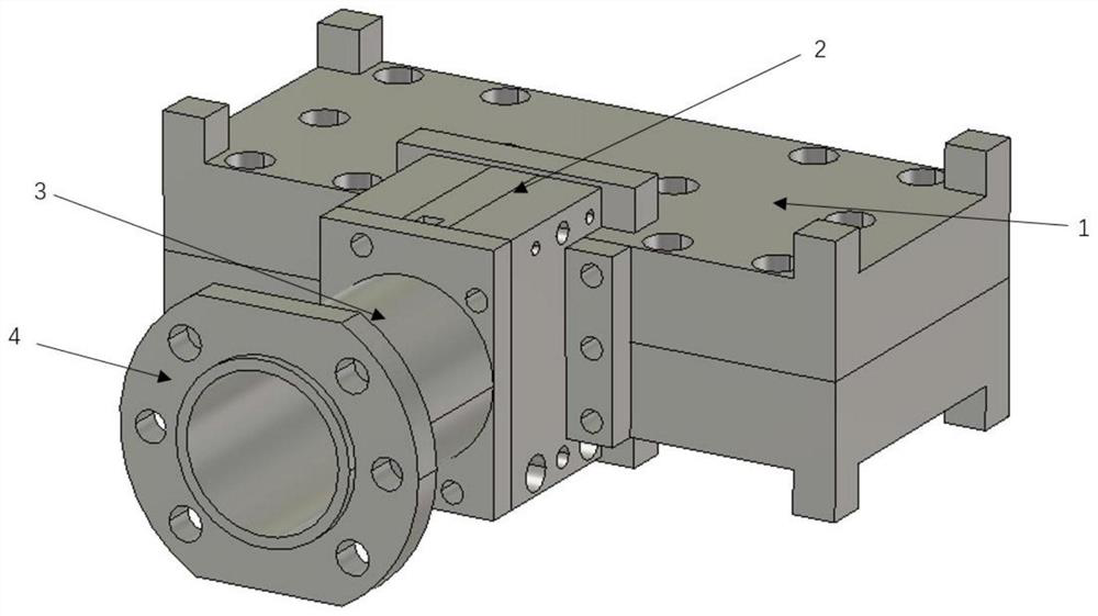
[0030] Such as figure 1 As shown, an all-metal structure Ka-band circular waveguideTM 11For the mode exciter, in order to ensure its structural strength, hard aluminum alloy is selected as its processing material. The mode exciter is composed of a power division structure 1 , a coupling excitation structure 2 and an output structure 3 , and is connected to a circular waveguide transmission link through a waveguide flange 4 .

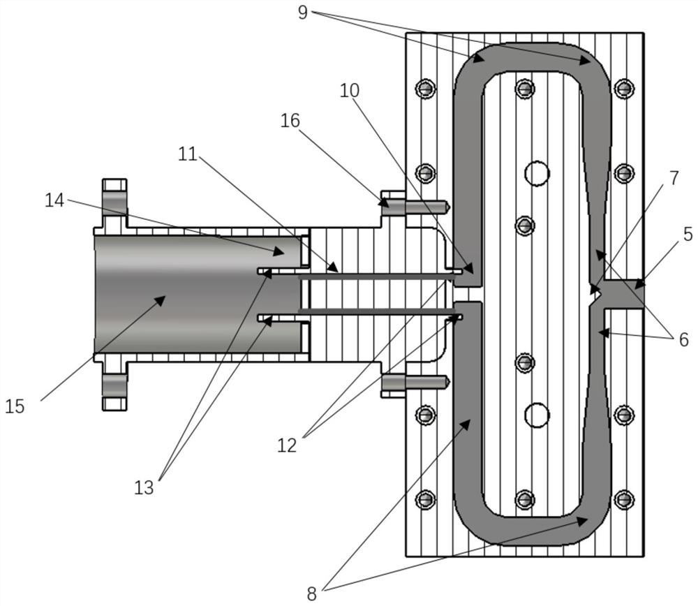
[0031] Such as figure 2 As shown, the power division structure 1 is a one-to-two power divider based on a rectangular waveguide, which is composed of a group of symmetrically arranged metal cover plates. The inner cavity between the metal covers forms a rectangular waveguide waveguide structure, including a rectangular waveguide E-plane T-junction, a gradu...


PUM


Abstract

The invention discloses a circular waveguide TM 11 The invention discloses a pattern exciter of a pattern, which belongs to the technical field of high-power millimeter wave testing. The mode exciter includes a power division structure, a coupling excitation structure and an output structure. TE 10 After the mode passes through the power division structure, it is divided into two groups of TE with equal amplitude and 180° phase difference. 10 The mode reaches the coupling end. At the coupling end, two sets of rectangular waveguides TE 10 The modes are efficiently coupled into the ridge-gap waveguide by the two coupling probes of the coupled excitation structure, and converted into two sets of quasi-TEM modes of the ridge-gap waveguide with equal amplitude and 180° phase difference, which are respectively transmitted to the two excitation probes by the ridge-gap waveguide. At the needle, a set of equal-amplitude and anti-phase TEM waves are excited at the excitation end of the output structure through the excitation probe. This group of TEM waves becomes a circular waveguide TM after vector synthesis 11 The mode is output to the circular waveguide transmission link through the output port. The mode exciter of the present invention can generate a circular waveguideTM in a broadband 11 Mode, the mode has high purity, small transmission loss, and compact structure, which is conducive to system integration.

Description

technical field [0001] The invention belongs to the technical field of high-power millimeter wave testing, in particular, relates to a method for generating a circular waveguide TM 11 Pattern exciter for pattern. Background technique [0002] The cyclotron traveling wave tube has the characteristics of high gain, wide frequency band and high power, and has a very broad application prospect in the fields of imaging radar, millimeter wave communication system, electronic countermeasures and microwave weapons. Common working mode of gyrotron traveling wave tube TE 01 The mode is not suitable as a feed radiation mode directly and needs to be converted into a Gaussian beam. Currently, it is commonly used to realize circular waveguide TE 01 Mode-oriented Gaussian beam or Gaussian-like field HE 11 The mode change sequence of the mode has the following two methods: TE 01 →TE 11 → HE 11 and TE 01 →TM 11 → HE 11 . Compared with the previous conversion sequence, using TM 11...

Claims


Application Information

Patent Timeline
Patent Type & Authority Patents(China)
IPC IPC(8): H01P1/163
CPCH01P1/163
Inventor 吴泽威王敏行蒲友雷蒋伟罗勇
Owner UNIV OF ELECTRONICS SCI & TECH OF CHINA
Why Eureka
Try Eureka