Intermediate infrared vector vortex light generating device and method

A technology for generating device and vortex light, which is applied in optics, lasers, optical components, etc., can solve the problems of unstable transmission and low purity of vector vortex beams, achieve high mode purity, solve unstable transmission, and solve problems with low purity. Effect

Pending Publication Date: 2022-05-13
SHENZHEN UNIV
View PDF14 Cites 0 Cited by
  • Summary
  • Abstract
  • Description
  • Claims
  • Application Information

AI Technical Summary

Problems solved by technology

[0006] The technical problem to be solved by the present invention is that, aiming at the defects of the prior art, the present invention provides a mid-infrared vector vortex light generation device and method to solve the low purity and unstable transmission of the vector vortex beam generated by the existing passive conversion method technical issues

Method used


Image

  • Intermediate infrared vector vortex light generating device and method
  • Intermediate infrared vector vortex light generating device and method
  • Intermediate infrared vector vortex light generating device and method

Examples


Embodiment 1

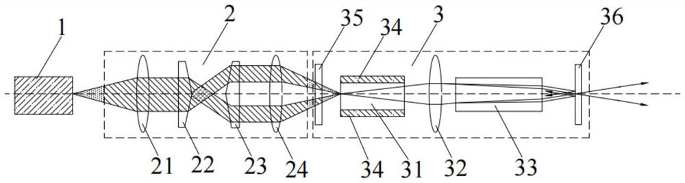
[0043] Such as figure 1 and figure 2 As shown, the embodiment of the present invention provides a mid-infrared vector vortex light generating device. The mid-infrared vector vortex light generating device includes: a pumping light source 1 for emitting a laser beam, which is arranged opposite to the pumping light source 1 and A shaping focusing structure 2 for adjusting the shape and size of the laser beam and a resonant cavity structure 3 arranged opposite to the shaping focusing structure 2 and used to generate a vector vortex beam;

[0044] The pump light source 1, the shaping focusing structure 2 and the resonant cavity structure 3 are sequentially arranged on the same optical axis, and the pumping light source 1, the shaping focusing structure 2 and the resonant cavity structure 3 are respectively Fixed connection with the base.

[0045]In this embodiment, the pump light source 1 can be used to provide a pump beam with a specified wavelength; the shaping focusing struc...

Embodiment 2

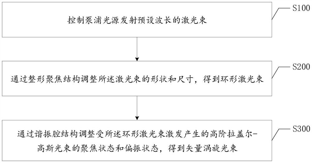
[0071] Such as image 3 As shown, the embodiment of the present invention provides a method for generating mid-infrared vector vortex light, and the method for generating mid-infrared vector vortex light includes the following steps:

[0072] Step S100, controlling the pumping light source to emit a laser beam with a preset wavelength.

[0073] In this embodiment, the method for generating mid-infrared vector vortex light is implemented based on the above-mentioned mid-infrared vector vortex light generating device; wherein, the structure of the mid-infrared vector vortex light generating device is specifically as described above.

[0074] In one implementation, the mid-infrared laser beam can be obtained by controlling the pumping light source to emit a laser beam with a preset wavelength; in this embodiment, a 976nm laser diode is used as the pumping light source to provide the pumping beam ; The pump light source can emit a pump beam with a wavelength of 976nm, so as to em...


PUM


Abstract

The invention discloses an intermediate infrared vector vortex light generating device and method. The device comprises a pump light source for emitting a laser beam, a shaping focusing structure which is arranged opposite to the pump light source and is used for adjusting the shape and size of the laser beam, and a resonant cavity structure which is arranged opposite to the shaping focusing structure and is used for generating a vector vortex beam, the pump light source, the shaping and focusing structure and the resonant cavity structure are sequentially arranged on the same optical axis and are fixedly connected with the base respectively. A laser beam emitted by a pumping source is shaped based on a shaping focusing structure of a conical lens group to obtain an annular light beam, a high-order Laguerre-Gaussian vortex light beam with a polarization characteristic is generated through a yttrium aluminum garnet crystal in a resonant cavity structure, o light and e light are separated by using a birefringent crystal, and the polarization of the laser is improved. Therefore, stable angular and radial vector polarization vortex beams are obtained, and stable output of spatial structure light in the middle-infrared band is realized.

Description

technical field [0001] The invention relates to the application field of solid-state lasers, in particular to a mid-infrared vector vortex light generating device and method. Background technique [0002] The mid-infrared laser can correspond to the transparent window of atmospheric transmission and cover many molecular absorption peaks, and has important applications in the fields of military, medical, remote sensing, and spectroscopy; and the vector vortex beam is a kind of beam with orbital angular momentum and beam cross-sectional polarization state Structured beams with anisotropic distribution; due to its unique helical phase structure and anisotropic distribution of polarization states, vector vortex beams have broad application prospects in the fields of optical communication, laser processing, ion manipulation and quantum technology. Therefore, how to generate vector vortex beams has attracted the attention of many scholars, and many achievements have been made. ...

Claims


Application Information

Patent Timeline
Patent Type & Authority Applications(China)
IPC IPC(8): H01S3/10H01S3/102H01S3/106H01S3/16G02B27/09
CPCH01S3/1022H01S3/10061H01S3/106H01S3/1643G02B27/0961
Inventor 刘军顾杰黄璐方志强赵婷
Owner SHENZHEN UNIV
Why Eureka
Try Eureka