Dual-confocal waveguide gyrotron traveling wave tube input coupler based on coaxial resonant cavity structure

A coaxial resonant cavity, input coupling technology, applied in the direction of the coupling device of the transit time type electron tube, etc., can solve the problems of difficult stray mode suppression, low conversion efficiency, complex structure of the mode input coupler, etc., to achieve simple structure, conversion Efficient and easy-to-process results

Pending Publication Date: 2022-07-22
UNIV OF ELECTRONICS SCI & TECH OF CHINA
View PDF5 Cites 0 Cited by
  • Summary
  • Abstract
  • Description
  • Claims
  • Application Information

AI Technical Summary

Problems solved by technology

[0006] In order to solve the double confocal waveguide gyrotraveling wave tube TE 0n The structure of the mode input coupler is complex, the suppression of mixed modes is difficult, and the conversion efficiency is low

Method used


Image

  • Dual-confocal waveguide gyrotron traveling wave tube input coupler based on coaxial resonant cavity structure
  • Dual-confocal waveguide gyrotron traveling wave tube input coupler based on coaxial resonant cavity structure
  • Dual-confocal waveguide gyrotron traveling wave tube input coupler based on coaxial resonant cavity structure

Examples


Embodiment Construction

[0018] The present invention will be further elaborated below in conjunction with a design example and the accompanying drawings. It is necessary to point out that this embodiment is only used to further illustrate the present invention, and should not be construed as a limitation on the protection of the present invention. Some non-essential improvements and adjustments can be made according to the content of the present invention described above.

[0019] The working band of this embodiment: 218-222GHz.

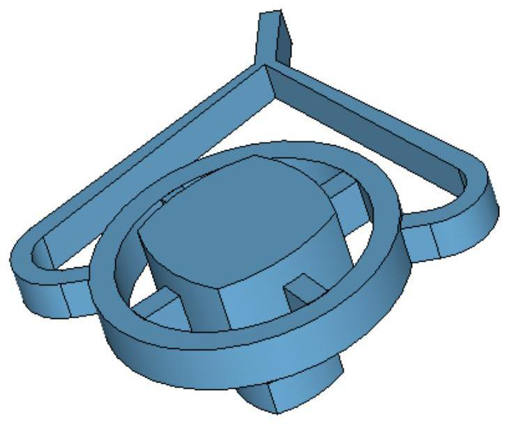
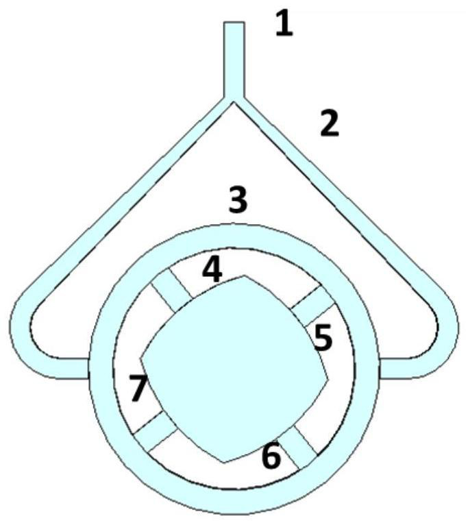
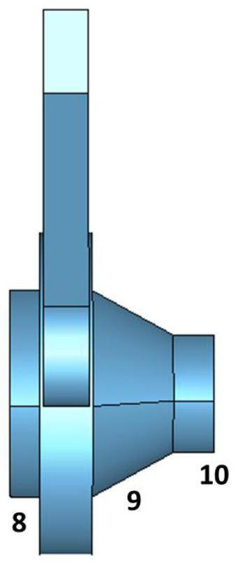
[0020] figure 1 It is a schematic diagram of the three-dimensional structure of the input coupler of the dual confocal waveguide gyro traveling wave tube based on the coaxial resonator structure; figure 2 is the front view of the input coupler; image 3 is a side view of the input coupler. This embodiment includes: a power distribution part: a standard rectangular waveguide 1 , a Y-shaped power division 2 , a coaxial resonant cavity 3 , and four-segment coupled waveguid...


PUM


Abstract

The invention discloses a dual confocal waveguide gyrotron traveling wave tube input coupler based on a coaxial resonant cavity structure, and belongs to the technical field of microwave and millimeter wave devices. The circuit comprises a power distribution part, a mode conversion part and a cut-off section part. A Y-shaped power divider is connected with a coaxial resonant cavity, so that four-path power distribution is realized. The mode of four paths of symmetrical feed sources is adopted, so that the beneficial effects of inhibiting a miscellaneous mode, reducing the reflection coefficient, improving the conversion efficiency and increasing the bandwidth are achieved.

Description

technical field [0001] The invention belongs to the technical field of microwave, millimeter wave and terahertz devices, in particular to a dual confocal waveguide gyroscopic traveling wave tube input coupler based on a coaxial resonant cavity structure, which can be applied to the gyrotron in the millimeter wave and terahertz bands wave tube. Background technique [0002] Gyro-travelling wave tube (Gyro-TWT) amplifier is a microwave electric vacuum device based on the electron cyclotron pulsation mechanism. It has broad application prospects in the fields of modern high-performance radar, long-distance communication technology, and electronic countermeasures. [0003] Traditional gyroscopic traveling wave tubes generally use circular waveguides as high-frequency interaction structures. In order to prevent parasitic oscillations from damaging the working state, they often work in low-order modes. However, when the gyroscopic traveling wave tube develops to a higher frequen...

Claims


Application Information

Patent Timeline
Patent Type & Authority Applications(China)
IPC IPC(8): H01J23/38H01J23/36
CPCH01J23/38H01J23/36
Inventor 刘頔威张晨王维
Owner UNIV OF ELECTRONICS SCI & TECH OF CHINA
Why Eureka
Try Eureka