
Photographing-based 3D modeling system and method and automatic 3D modeling device and method

A 3D, shooting position technology, applied in the field of 3D modeling system, can solve problems such as large amount of calculation, modeling failure, long time consumption, etc., and achieve the effect of low cost and wide range of shooting methods

Active Publication Date: 2020-02-07
SHANG HAI YIWO INFORMATION TECH CO LTD
View PDF13 Cites 24 Cited by
  • Summary
  • Abstract
  • Description
  • Claims
  • Application Information

AI Technical Summary

Problems solved by technology

[0006] Disadvantage 1: The amount of calculation is large, and it is not easy to model on devices with limited computing resources such as mobile devices. Usually, it needs to be uploaded to the server (cloud / PC) to use stronger computing power to run the modeling algorithm;
[0007] Disadvantage 2: It is impossible to give a specification for how far to shoot at a specific interval. If it is too dense, it will be too troublesome to use and takes too long; if it is only visible by two or two, it may fail to model, and the user cannot be prompted when shooting
[0008] In addition, methods for reconstructing 3D space scenes based on photographs have been provided in the past, but these methods basically cannot automatically generate 3D models based on images used for 3D modeling, and require a lot of manual intervention to correct the 3D models of each space
In addition, it is impossible to automatically splice the 3D models of multiple spaces. It is necessary to manually observe the 3D models of each space and find out the common points, and then manually stitch them together, which is time-consuming and labor-intensive.

Method used

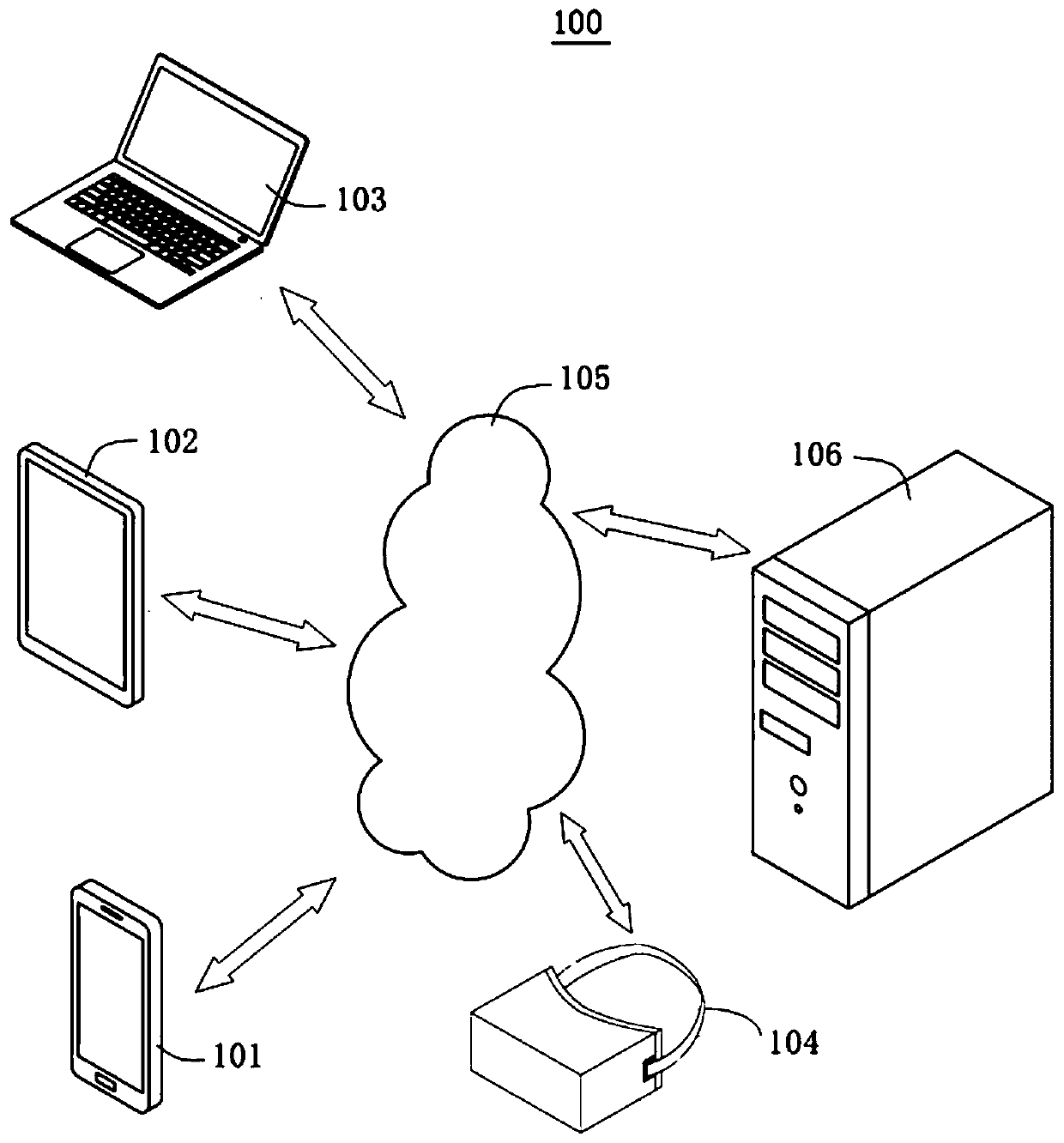
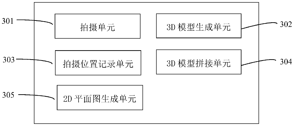

Image

  • Photographing-based 3D modeling system and method and automatic 3D modeling device and method
  • Photographing-based 3D modeling system and method and automatic 3D modeling device and method
  • Photographing-based 3D modeling system and method and automatic 3D modeling device and method

Examples


Embodiment Construction

[0058] Unless otherwise defined, all technical and scientific terms used herein have the same meaning as commonly understood by those skilled in the technical field of the present invention; the terms used herein in the description of the application are only to describe specific embodiments The purpose is not to limit the present invention; the terms "comprising" and "having" and any variations thereof in the specification and claims of the present invention and the description of the above drawings are intended to cover non-exclusive inclusion. The terms "first", "second" and the like in the description and claims of the present invention or the above drawings are used to distinguish different objects, rather than to describe a specific order.

[0059]Reference herein to an "embodiment" means that a particular feature, structure, or characteristic described in connection with the embodiment can be included in at least one embodiment of the present invention. The occurrences ...


PUM


Abstract

The invention discloses a photographing-based 3D modeling system and method , and an automatic 3D modeling device and method. The photographing-based 3D modeling method comprises the following steps:S1) fixing a mobile device and a camera on the same photographing bracket; S2) acquiring a plurality of images for positioning of the camera or the mobile equipment in the process of moving the bracket, and acquiring the position and orientation of each shooting point to form a route map using a unified coordinate system; S3) performing 3D modeling on the mobile device or the remote server based on the 3D modeling image of each shooting point; and S4) uniformly placing the 3D model of each shooting point in the same three-dimensional coordinate system according to the position and orientationobtained in the step S2, and splicing the joint parts of the 3D models of the plurality of shooting points to form an overall 3D model containing the plurality of shooting points. According to the photographing-based 3D modeling method, various shooting devices can be supported, and the relative position of each shooting point and the lens orientation of the camera can be automatically and accurately recorded, and a 3D model and a 2D planar graph which can roam inside can be automatically generated.

Description

technical field [0001] The present invention relates to a 3D modeling system and method, in particular to a camera-based 3D modeling system and method, an automatic 3D modeling device and method. Background technique [0002] The technical problem to be solved by the present invention is a three-dimensional space modeling scheme based on photography, which can be used for single-space or multi-space 3D modeling and / or 2D plan generation. [0003] In the past, there were mainly two types of 3D modeling methods based on photography, but both had obvious disadvantages: [0004] Method a) Use a camera capable of recognizing depth information to directly generate a 3D model. This method relies on more complex hardware, resulting in higher equipment costs, and often requires professional photographers to operate, which is not conducive to popularization; [0005] Method b) Take two photos at a place where the shooting point is relatively close, preferably at the centimeter level...

Claims


Application Information

Patent Timeline
Patent Type & Authority Applications(China)
IPC IPC(8): H04N13/106H04N13/275H04N13/293
CPCH04N13/106H04N13/275H04N13/293G06T17/00
Inventor 赵明向中正蔡锫
Owner SHANG HAI YIWO INFORMATION TECH CO LTD
Learn More