Gas pressure restriction valve for controlling and emitting gaseous media

A technology of gas pressure and gaseous medium, applied in the field of pressure limiting valve, can solve problems such as component damage, and achieve the effects of reducing wear, reducing surface size and avoiding pressure pulses

Active Publication Date: 2022-08-05
ROBERT BOSCH GMBH
View PDF9 Cites 0 Cited by
  • Summary
  • Abstract
  • Description
  • Claims
  • Application Information

AI Technical Summary

Problems solved by technology

This may result in damage to both components

Method used


Image

  • Gas pressure restriction valve for controlling and emitting gaseous media
  • Gas pressure restriction valve for controlling and emitting gaseous media
  • Gas pressure restriction valve for controlling and emitting gaseous media

Examples


Embodiment Construction

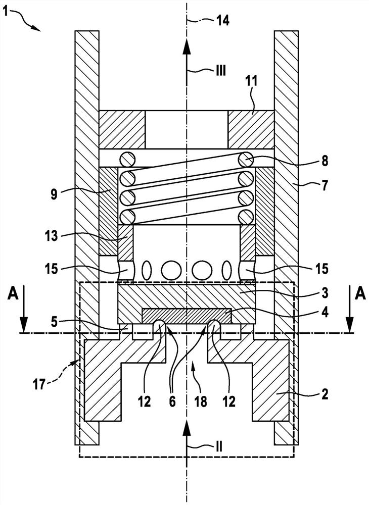
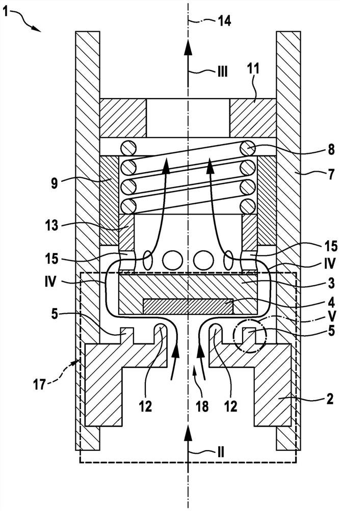
[0027] according to figure 1 and figure 2 The illustration of 1 shows an embodiment of a pressure limiting valve 1 , in particular a gas pressure limiting valve 1 , for controlling and discharging gaseous media.

[0028] as from figure 1 It can be seen that the gas pressure limiting valve 1 comprises a housing 7 , a valve element mounting assembly 17 , a sleeve-shaped element 13 supporting the closing spring 8 , in particular a guide element 9 for guiding the closing spring 8 and a closing spring support 11 . Furthermore, the valve element mounting assembly 17 has a sealing seat plate 2 and a valve element 3 , wherein the valve element 3 is in contact with the sleeve-shaped element 13 in the direction of the longitudinal axis 14 or, in an alternative embodiment, with the sleeve-shaped element 13 Connections. In addition, the sleeve-shaped element 13 has at least one passage opening 15 , which enables a flow of gas from the inflow II to the outflow III in the direction of t...


PUM


Abstract

The invention relates to a gas pressure limiting valve (1) for controlling a gaseous medium, in particular hydrogen, the gas pressure limiting valve having a housing (7) and a valve element mounting assembly (17), wherein the valve element is mounted The assembly ( 17 ) has a valve element ( 3 ) that opens and closes in the direction of the longitudinal axis ( 14 ) and is thus movable and has an immovable sealing seat plate ( 2 ), wherein, or the sealing seat plate ( 2 ) Alternatively, the valve element ( 3 ) has a sealing seat edge ( 12 ) which surrounds the longitudinal axis ( 14 ) and forms a seal with the corresponding other component in the closed state of the valve ( 1 ) seat (6), the gas pressure limiting valve having a closing spring (8) arranged in the housing (7) in the direction of the longitudinal axis (14), and wherein the closing spring (8) on one side in the direction of the longitudinal axis (14) on the closing spring support (11) and on the opposite side at least indirectly on the valve element (3), According to the invention, the valve element ( 3 ) or the sealing seat plate ( 2 ) has an elastomer coating ( 4 ) which, in the closed state of the valve ( 1 ), is Alternatively, the sealing seat edge (12) of the sealing seat plate (2) or the sealing seat edge of the valve element (3) forms the sealing seat (6), the sealing seat plate (2) or the sealing seat edge (6). The valve element (3) has a circumferential stop (5), and the circumferential seal seat edge (12) is limited by the circumferential stop (5) to the elastomer cover in the direction of the longitudinal axis (14). The extrusion depth in layer (4).

Description

technical field [0001] The invention relates to a pressure limiting valve, in particular a gas pressure limiting valve, for controlling and venting a gaseous medium, especially hydrogen, having a valve element mounting assembly, in particular for use in vehicles with fuel cell drives. Background technique [0002] In the field of vehicles, in addition to liquid fuels, gaseous fuels will also become increasingly important in the future. Especially in vehicles with fuel cell drives the flow of hydrogen must be controlled. In this case, the gas flow is no longer controlled discontinuously, as in the case of liquid fuel injection, but the gas is extracted from the at least one high-pressure tank and directed to the injector unit via the inflow line of the medium-pressure line system. The injector unit leads the gas to the fuel cell via the connecting lines of the low-pressure line system. [0003] A pressure limiting valve is known from DE 10 2013 204 563 A1 with a housing and...

Claims


Application Information

Patent Timeline
Patent Type & Authority Patents(China)
IPC IPC(8): F16K17/04F16K1/42F02M63/00F02M21/02
CPCF16K17/0426F16K17/0466F02M21/0239
Inventor H-C·马格尔
Owner ROBERT BOSCH GMBH
Why Eureka
Try Eureka