Cleaning device for glass processing

A cleaning device and glass technology, applied in the direction of cleaning method using tools, cleaning method using liquid, cleaning flexible objects, etc., can solve the problems of inability to effectively transport glass, affecting cleaning and transportation, glass friction resistance, etc., and achieve a simple structure. , Easy to operate, to ensure the effect of cleaning strength

Inactive Publication Date: 2020-02-11
徐州市威固特种玻璃有限公司
View PDF11 Cites 2 Cited by
  • Summary
  • Abstract
  • Description
  • Claims
  • Application Information

AI Technical Summary

Problems solved by technology

[0003] For example, the Chinese Patent Publication No. is CN110280510A, which discloses a circulating cleaning device for glass processing. The device is provided with a disk brush on the top of the supporting frame for feeding to clean the glass, but the spraying needs to apply a certain amount of water to the glass during the cleaning process. With a certain pressure, the dirt on the outer wall of the glass is removed by friction, which will cause the glass to be subjected to frictional resistance, resulting in the inability to effectively convey the glass, and the inability of the glass to move will affect cleaning and conveying, resulting in low production efficiency

Method used


Image

  • Cleaning device for glass processing
  • Cleaning device for glass processing
  • Cleaning device for glass processing

Examples


Embodiment 1

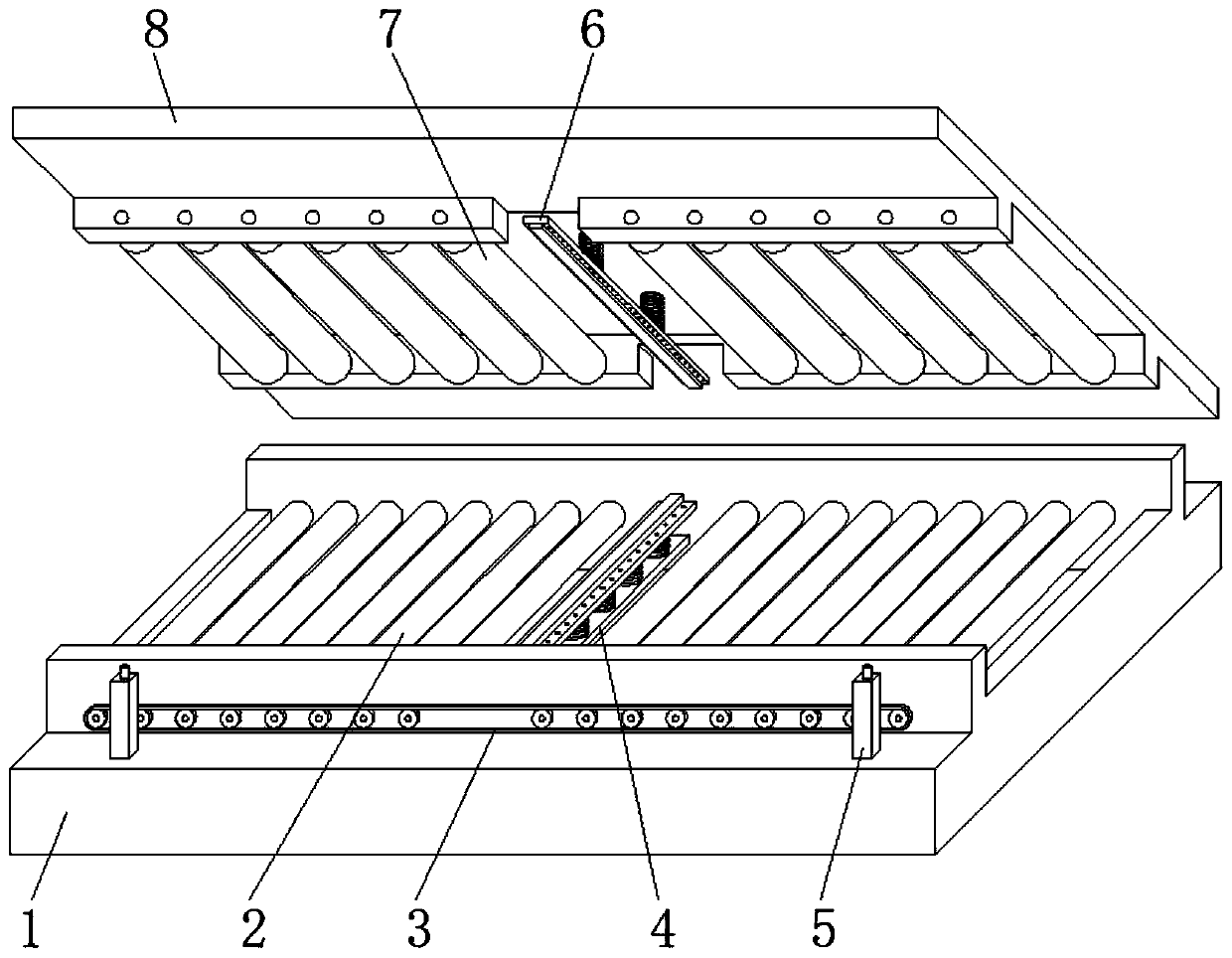
[0025] refer to Figure 1-2 , a cleaning device for glass processing, comprising a base 1, a hydraulic cylinder 5 is fixed on both sides of the top outer wall of the base 1 by screws, and a top plate 8 is fixed on the top of the piston rod of the hydraulic cylinder 5 by screws, and the inner wall of the top plate 8 is provided with Press roller installation hole, and the inwall of press roller installation hole is connected with press roller 7 by bearing, and the inwall of base 1 has delivery roller installation hole, and the inwall of delivery roller installation hole is connected with delivery roller 2 by bearing.

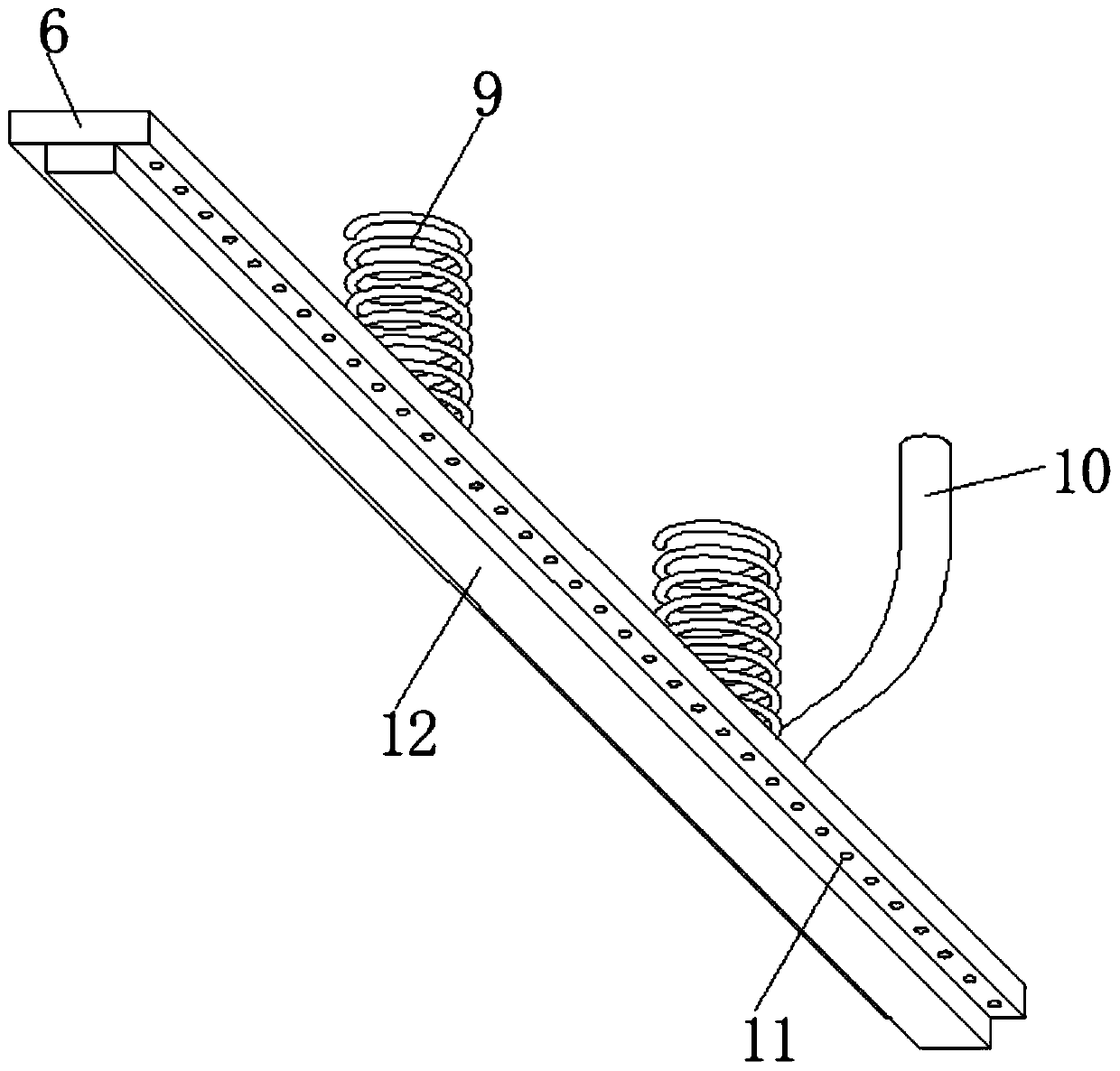
[0026] In the present invention, the middle part of the inner wall of the base 1 is welded with a supporting plate 4, and the top outer wall of the supporting plate 4 and the top inner wall of the top plate 8 are welded with a buffer spring 9, and one end of the buffer spring 9 is welded with a water spray pipe 6.

[0027] In the present invention, water spray ho...

Embodiment 2

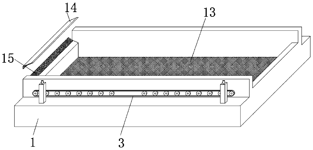
[0033] refer to image 3 , a glass cleaning device, one side of the top outer wall of the base 1 and one side of the top inner wall of the top plate 8 are welded with shrapnel 14, and the outer walls of the opposite sides of the two shrapnel 14 are pasted with absorbent cotton 15, the glass from both sides When passing out between two shrapnels 14, absorbent cotton 15 wipes the moisture on the glass surface.


PUM


Abstract

The invention discloses a cleaning device for glass processing. The cleaning device comprises a base. Hydraulic cylinders are fixed to the two sides of the top outer wall of the base through screws correspondingly. A top plate is fixed to the top ends of piston rods of the hydraulic cylinders through screws. Pressing roller installing holes are formed in the inner wall of the top plate. Pressing rollers are connected with the inner walls of the pressing roller installing holes through bearings. Conveying roller installing holes are formed in the inner wall of the base. Conveying rollers are connected with the inner walls of the conveying roller installing holes through bearings. A supporting plate is welded to the middle of the inner wall of the base. Buffering springs are welded to the top outer wall of the supporting plate, and buffering springs are welded to the top inner wall of the top plate. A water spraying pipe is welded to one end of each buffering spring. Certain squeezing force can be exerted on glass, the friction force between the glass and the conveying rollers is ensured, the glass conveying efficiency can be easily ensured, and the cleaning device is suitable for glass with different thicknesses, is beneficial for ensuring the cleaning intensity, can recover water and meanwhile improves the protection on the working environment.

Description

technical field [0001] The invention relates to the technical field of glass processing equipment, in particular to a cleaning device for glass processing. Background technique [0002] Glass needs to be cleaned during processing to remove stains, dust and other impurities adhering to the outer wall of the glass. In order to meet market demand, cleaning is generally carried out while the glass is being conveyed. The glass is cleaned by setting a spraying mechanism and a brushing mechanism on the conveying line. [0003] For example, the Chinese Patent Publication No. is CN110280510A, which discloses a circulating cleaning device for glass processing. The device is provided with a disk brush on the top of the supporting frame for feeding to clean the glass, but the spraying needs to apply a certain amount of water to the glass during the cleaning process. With a certain pressure, the dirt on the outer wall of the glass is removed by friction, which will cause the glass to be ...

Claims


Application Information

Patent Timeline
Patent Type & Authority Applications(China)
IPC IPC(8): B08B11/04B08B3/02B08B1/02B08B13/00
CPCB08B1/02B08B3/022B08B11/04B08B13/00
Inventor 宋庆
Owner 徐州市威固特种玻璃有限公司
Why Eureka
Try Eureka