Unexploded ordnance destruction device and method

A technology of destroying devices and unexploded bombs, which is applied in the directions of manipulators, chucks, and manufacturing tools, etc., can solve the problems of high price of EOD robots, large direct economic losses, and reduced success rate of detonation. Operator requirements, the effect of improving the success rate and reducing the cost of bomb discharge

Pending Publication Date: 2020-02-11
苏州融萃特种机器人有限公司
View PDF0 Cites 1 Cited by
  • Summary
  • Abstract
  • Description
  • Claims
  • Application Information

AI Technical Summary

Problems solved by technology

However, if a conventional EOD robot grabbing device, such as a three-claw manipulator or a two-claw manipulator, is used to grab unexploded bombs, the position of the central axis of the unexploded bombs is not easy to determine, which brings a lot of problems to the detonation of perforating bombs. Reduce the uncertainty and reduce the success rate of detonation
Moreover, EOD robots are expensive. If the EOD robots are damaged to a greater extent when destroying unexploded bombs, the direct economic loss will be greater.

Method used


Image

  • Unexploded ordnance destruction device and method
  • Unexploded ordnance destruction device and method
  • Unexploded ordnance destruction device and method

Examples


Embodiment Construction

[0040] The present invention will be described in detail below with reference to the accompanying drawings and in combination with embodiments. The descriptions here are used to provide a further understanding of the present invention and constitute a part of the application. The exemplary embodiments of the present invention and their descriptions are used to explain the present invention and do not constitute improper limitations to the present invention.

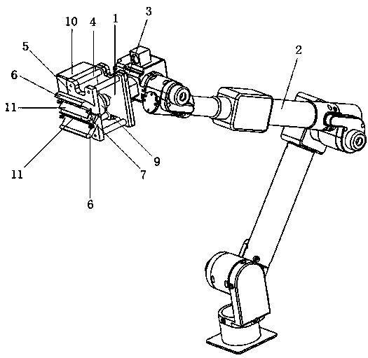
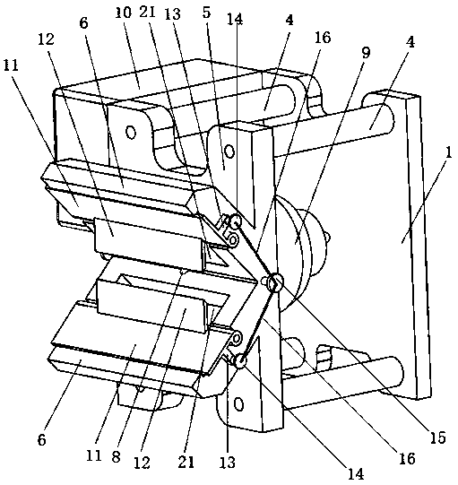
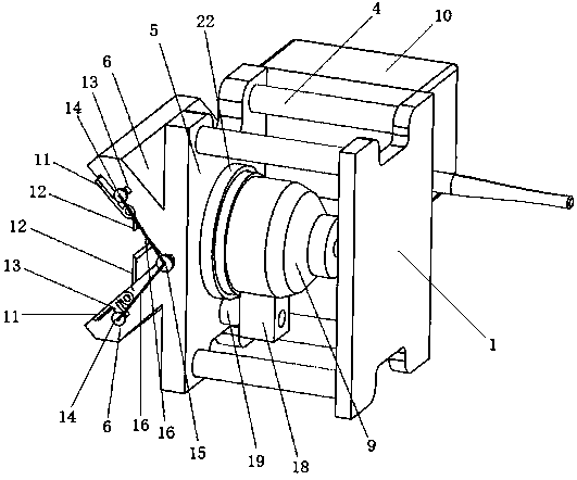
[0041] see Figure 1-8 As shown, a device for destroying unexploded bombs includes a bottom plate 1 that can be electromagnetically adsorbed, and the back side of the bottom plate 1 is used to connect with the mechanical arm electromagnet 3 at the front end of the robotic arm 2 by electromagnetic adsorption. The front of the bottom plate 1 is equipped with an electromagnetic gripper through several connecting rods 4, and the electromagnetic gripper is composed of a gripper connecting plate 5 and two gripper supporting pla...


PUM


Abstract

The invention discloses an unexploded ordnance destruction device and method. The device includes a bottom plate which can be attracted by a mechanical arm electromagnet, an electromagnetic gripper isinstalled on the front side of the bottom plate through a connecting rod, a gripper electromagnet is arranged in the electromagnetic gripper, the bottom of a V-shaped groove of the electromagnetic gripper is provided with a jet hole, a perforating bullet device aligning at the jet hole is arranged on the back face of the electromagnetic gripper, and a wireless receiver is arranged on one side ofthe electromagnetic gripper; and the two walls of the V-shaped groove are provided with turnover limit plates, and the two ends of each limit plate are connected to fixed pins at the two ends of the bottom of the V-shaped groove through tension springs. By means of the unexploded ordnance destruction device and method, the electromagnets and the V-shaped groove with the limit plates are used for grabbing and positioning an unexploded ordnance, and then the perforating bullet device is used for detonating and destroying the unexploded ordnance, so that the operation difficulty of ordnance fetching and the requirements for operators are reduced, the success rate of ordnance disposal is improved, the risk of work is reduced, the unexploded ordnance can be safely and efficiently destroyed on the spot, detonation of the unexploded ordnance is separated from the robot, damage to the robot is avoided, and the ordnance disposal cost is reduced.

Description

technical field [0001] The invention belongs to the technical field of unexploded bomb removal, and in particular relates to an unexploded bomb destruction device and method thereof. Background technique [0002] Due to the influence of production process, manufacturing cost, actual working conditions and other factors, ammunition usually has a certain misfire rate, so a large number of unexploded bombs are often produced during the training process. However, these unexploded bombs have great potential safety hazards, and are likely to explode under the influence of the external environment, seriously threatening the safety of surrounding personnel and equipment. Therefore, it is necessary to take measures to destroy these unexploded bombs as soon as possible. [0003] Most of the traditional methods of destroying unexploded bombs use TNT to detonate. This method is not only inefficient, but also very dangerous. Nowadays, perforating bullets are often used to detonate unexp...

Claims


Application Information

Patent Timeline
Patent Type & Authority Applications(China)
IPC IPC(8): B25J11/00B25J15/06
CPCB25J11/0025B25J15/0608
Inventor 李永高陆树显方健梅涛李向威张明余涛
Owner 苏州融萃特种机器人有限公司
Why Eureka
Try Eureka