
Ventilation duct and compost ventilation device

A technology for ventilation pipes and ventilation devices, which is applied in the direction of fertilization devices, pipe components, organic fertilizers, etc., and can solve the problems of uneven ventilation in the composting system and non-vertical airflow axes of the air ducts, so as to improve the uniformity of air supply and reduce the The effect of ventilation dead ends

Active Publication Date: 2021-08-27
ACADEMY OF PLANNING & DESIGNING OF THE MINIST OF AGRI
View PDF0 Cites 0 Cited by
  • Summary
  • Abstract
  • Description
  • Claims
  • Application Information

AI Technical Summary

Problems solved by technology

[0005] In view of this, the present invention aims to provide a ventilation duct and a compost ventilation device to solve the problem that the air outlet airflow of the air duct near the air inlet is not perpendicular to the axis of the ventilation duct, and further solve the problem that the ventilation weak area is near the air inlet , reduce and improve the current situation of uneven ventilation in the composting system

Method used


Image

  • Ventilation duct and compost ventilation device
  • Ventilation duct and compost ventilation device
  • Ventilation duct and compost ventilation device

Examples


Embodiment

[0058] Further description will be given below through the embodiments shown in the accompanying drawings.

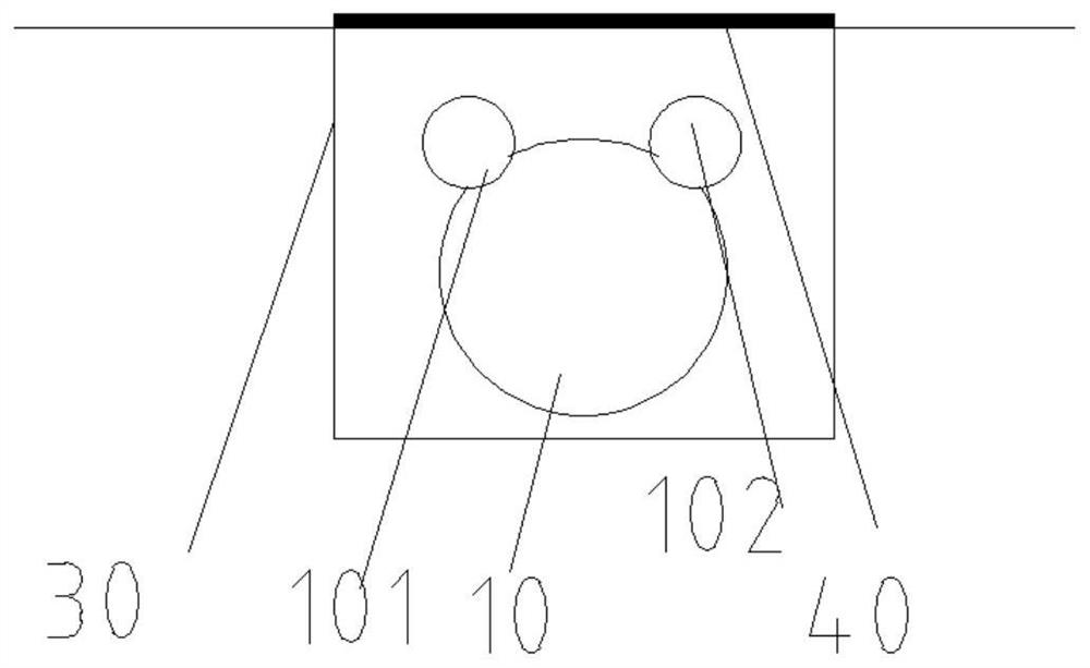
[0059] The ventilation pipe 10 of this embodiment is laid in the aeration tank 30, and the perforated plate 40 is laid on the tank to separate the pile body from the ventilation pipe. Ventilation duct 10 top offers ventilation hole 101, and baffle plate 102 is added on the ventilation hole 101, and when ventilating, baffle plate 102 is opened, as image 3 shown.

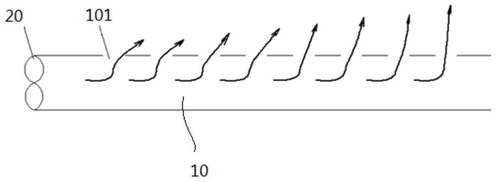
[0060] The ventilation ducts commonly used in the existing composting production, at the beginning of the duct, the flow velocity in the duct is high, and the outlet flow from the orifice is deflected to the axial direction of the duct, resulting in a weak ventilation area at the beginning of the duct; , so that the air velocity in the end area is too large, such as figure 1 shown.

[0061] Therefore, in order to improve the structure of the above-mentioned ventilation duct, on the basis of the existing com...


PUM

PropertyMeasurementUnit
thicknessaaaaaaaaaa

Abstract

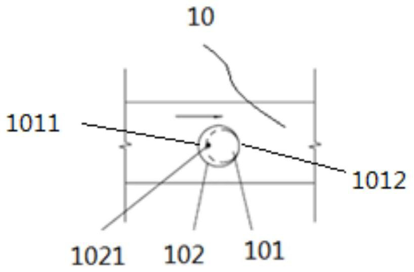
The invention relates to a ventilation pipe and a composting ventilation device. The ventilation duct includes a ventilation hole and a baffle, the ventilation hole is arranged on the peripheral surface of the ventilation duct, the ventilation hole includes a front end and a rear end, and the front end is closer to the air inlet of the ventilation duct One side of the ventilation hole, the rear end is the side farther away from the air inlet of the ventilation duct; the baffle plate is arranged on the ventilation hole, and the baffle plate is connected to On the ventilation duct, the baffle covers the ventilation hole when closed; the front end of the corresponding ventilation hole has a through hole when the baffle is closed, and the through hole is used for ventilating the ventilation duct. Air flow is passed to open the flap. The invention enables the air outlet air flow to form a wall-attached jet flow under the action of the baffle, so as to achieve the effect that the air outlet air flow is as perpendicular as possible to the axis of the air pipe, reduces the dead angle of ventilation, and improves the uniformity of air supply in the pipeline.

Description

technical field [0001] The invention relates to the technical field of pipeline ventilation, in particular to a ventilation pipeline and a compost ventilation device. Background technique [0002] Ventilation provides oxygen to the pile and removes waste heat and water vapor. When the ventilation is insufficient, the compost will undergo anaerobic fermentation, resulting in compost failure. Therefore, in actual production, in order to ensure the composting effect, an additional ventilation device will be added. In the current composting system with aeration tanks, an aeration tank is usually set up at the bottom of the pile, and ventilation pipes are laid in the grooves, and a perforated plate is laid on the grooves to separate the piles and ventilation pipes. A small hole is opened on the ventilation duct, and the air flow enters the pile body through the small hole. In order to reduce production costs, the ventilation system using positive pressure air supply has no oth...

Claims


Application Information

Patent Timeline
Patent Type & Authority Patents(China)
IPC IPC(8): F16L55/07C05F17/979
CPCY02W30/40
Inventor 程琼仪孟海波沈玉君程红胜
Owner ACADEMY OF PLANNING & DESIGNING OF THE MINIST OF AGRI
Learn More