Cleaning device for cleaning rotor plate of spinning rotor with cleaning head

A cleaning device, cleaning head technology, applied in the direction of spinning machine, open-end spinning machine, cleaning method and utensils, etc., can solve the problem of angle deviation, cleaning head spinning rotor misalignment, insufficient maintenance Spinning rotor and other problems to achieve the effect of avoiding slippage

Inactive Publication Date: 2020-02-11
MASCHINENFABRIK RIETER AG
View PDF1 Cites 0 Cited by
  • Summary
  • Abstract
  • Description
  • Claims
  • Application Information

AI Technical Summary

Problems solved by technology

However, constant misalignment of the cleaning head relative to the spinning rotor, e.g. due to an angular offset between the cleaning head and the spinning rotor, can result in insufficient cleaning
It can also happ

Method used


Image

  • Cleaning device for cleaning rotor plate of spinning rotor with cleaning head
  • Cleaning device for cleaning rotor plate of spinning rotor with cleaning head
  • Cleaning device for cleaning rotor plate of spinning rotor with cleaning head

Examples


Embodiment Construction

[0040] In the following description of the figures, the same reference numerals are used for identical and / or at least equivalent features in the various exemplary embodiments with respect to their design and / or mode of action. If certain features are not reproduced in detail in a certain figure, their design and / or mode of operation correspond to those of the features described above with reference to other figures. Also, generally only a corresponding one of a plurality of like features or components is illustrated and labeled in the figures for the sake of clarity.

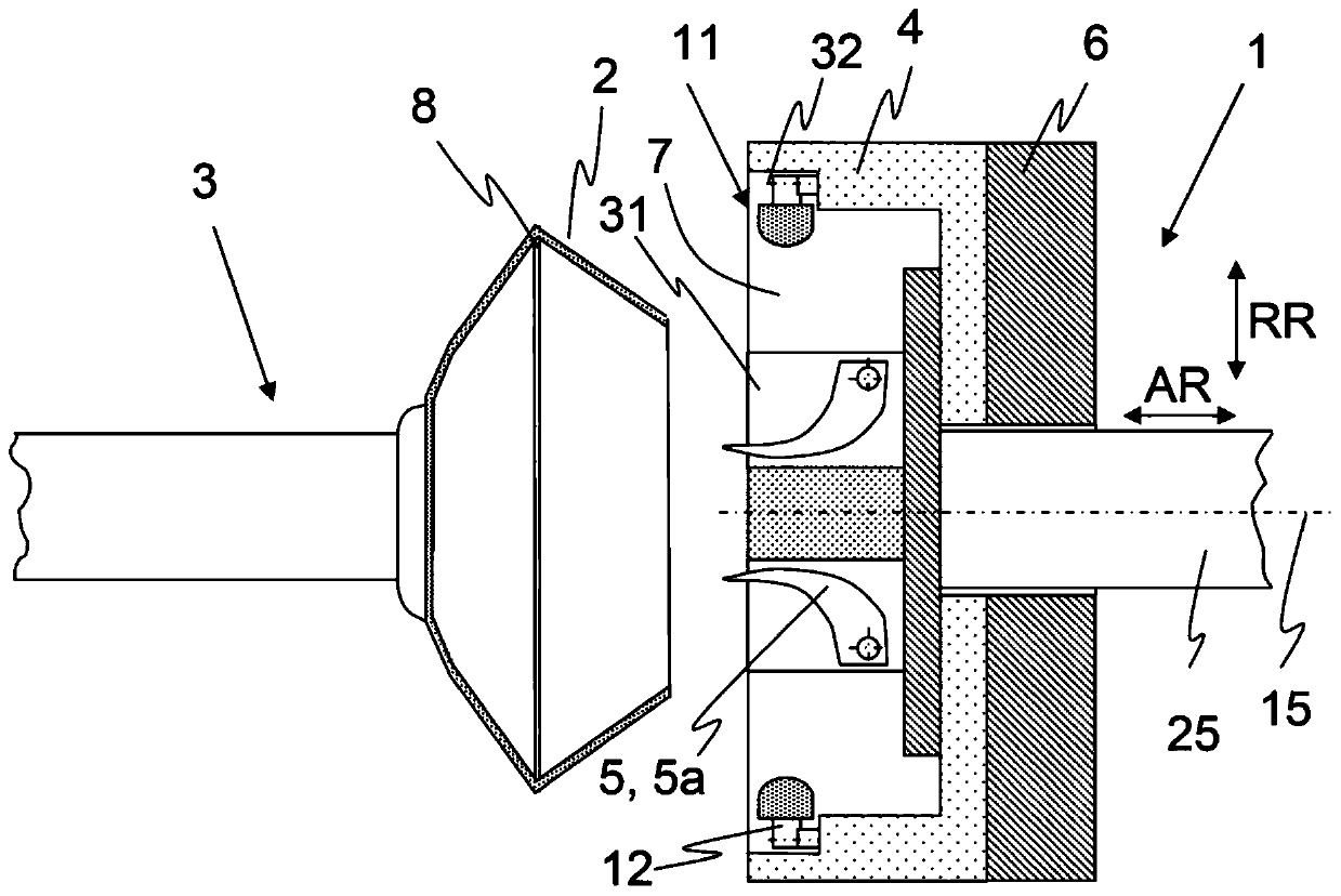
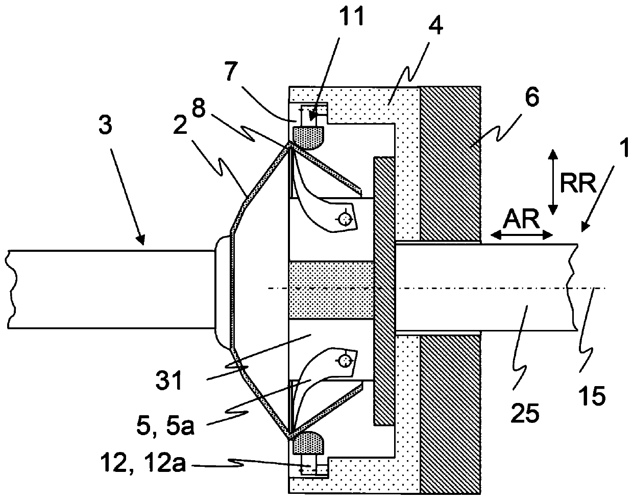
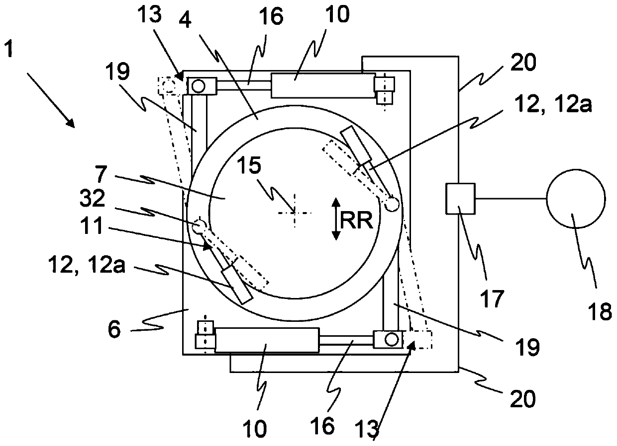
[0041] figure 1 A schematic side sectional view of a cleaning device 1 for cleaning a rotor disk 2 of a spinning rotor 3 is shown. The spinning rotor 3 is built into the spinning box of the free-end spinning machine as usual (the spinning box and the spinning machine are not shown in this figure, only in the Figure 8 A spinning machine 24 is shown schematically in ) and is used to spin the fiber material int...


PUM


Abstract

A cleaning device (1) for cleaning a rotor plate (2) of a spinning rotor (3) comprises a receptacle (6), a cleaning head (4) mounted on the receptacle (6), which can be advanced toward the spinning rotor (3) for cleaning and which includes at least one cleaning element (5, 5a, 5b), and comprising a brake device (11) for decelerating and/or holding the spinning rotor (3) once the cleaning head (4)has been advanced. The cleaning head (4) comprises an at least partially cylindrical receiving area (7) for the spinning rotor (3), which defines an axial direction (AR) and a radial direction (RR) ofthe cleaning head (4). The brake device (11) contains multiple, in particular two, brake elements (12), which are mounted on the cleaning head (4) in such a way that they are movable from a neutral position into a braking position, and each of the multiple brake elements (12) is movable with the aid of its own drive (13).

Description

technical field [0001] The invention relates to a cleaning device for cleaning a rotor disk of a spinning rotor, which comprises: an accommodating part; a cleaning head supported on the accommodating part, and the cleaning head can be pushed toward the spinning rotor for cleaning and having at least one cleaning element; and braking means for braking and / or holding the spinning rotor in the advancing cleaning head. In this case, the cleaning head has a receiving area for the spinning rotor which is at least partially cylindrical and defines the axial direction and the radial direction of the cleaning head. Background technique [0002] DE 33 13 926 A1 already discloses a cleaning device for a spinning rotor, in which cleaning brushes are introduced as cleaning elements into the spinning rotor in order to clean the fiber collection groove of the spinning rotor. The cleaning device is provided with a bell brake having brake pads on its edge. The cleaning head of the cleaning...

Claims


Application Information

Patent Timeline
IPC IPC(8): D01H4/24
CPCD01H4/24B08B13/00
Inventor H·威德纳塞巴斯蒂安·弗里茨
Owner MASCHINENFABRIK RIETER AG
Why Eureka
Try Eureka