Floor drain and mounting structure and production process thereof

A technology of installation structure and production process, applied in water supply devices, drainage structures, chemical instruments and methods, etc., can solve the problems of low material cost advantage, large thickness, and many consumables, achieve material cost control, ensure installation stability, Strong installation effect

Pending Publication Date: 2020-02-11
厦门盛腾发工贸有限公司
View PDF3 Cites 2 Cited by
  • Summary
  • Abstract
  • Description
  • Claims
  • Application Information

AI Technical Summary

Problems solved by technology

[0005] However, the inventor has been engaged in the production of floor drains for many years and found that in order to ensure that the grate plate will not be directly detached from the floor drain body due to water impact or slight touch by bathers during use, the thickness of the grate plate generally needs to be kept at 3 -4mm, so the depth of the stepped groove also needs to be set between 3-4mm (within this range, the grate plate has a certain weight and will not move directly due to the impact of spray water, and at the same time has a movement in the vertical direction The moving distance is required, the grate plate will not be lifted directly because of the user's slight touch), and because the stepped groove is also set on the installation part, and the installation part needs to reserve a certain thickness, at the same time, the installation part also needs to ensure There is a sufficient connection area with the installation port to ensure the stability of the floor drain during installation. For details, please refer to Chinese patents such as CN107060052B, CN103452184B, and CN106049648B. Therefore, in the prior art, the thickness of the installation part is generally 6-7mm. Larger thickness, more consumables, material cost advantage is too low, so it needs to be improved

Method used


Image

  • Floor drain and mounting structure and production process thereof
  • Floor drain and mounting structure and production process thereof
  • Floor drain and mounting structure and production process thereof

Examples


Embodiment Construction

[0047] The present invention will be described in detail below in conjunction with the accompanying drawings and embodiments.

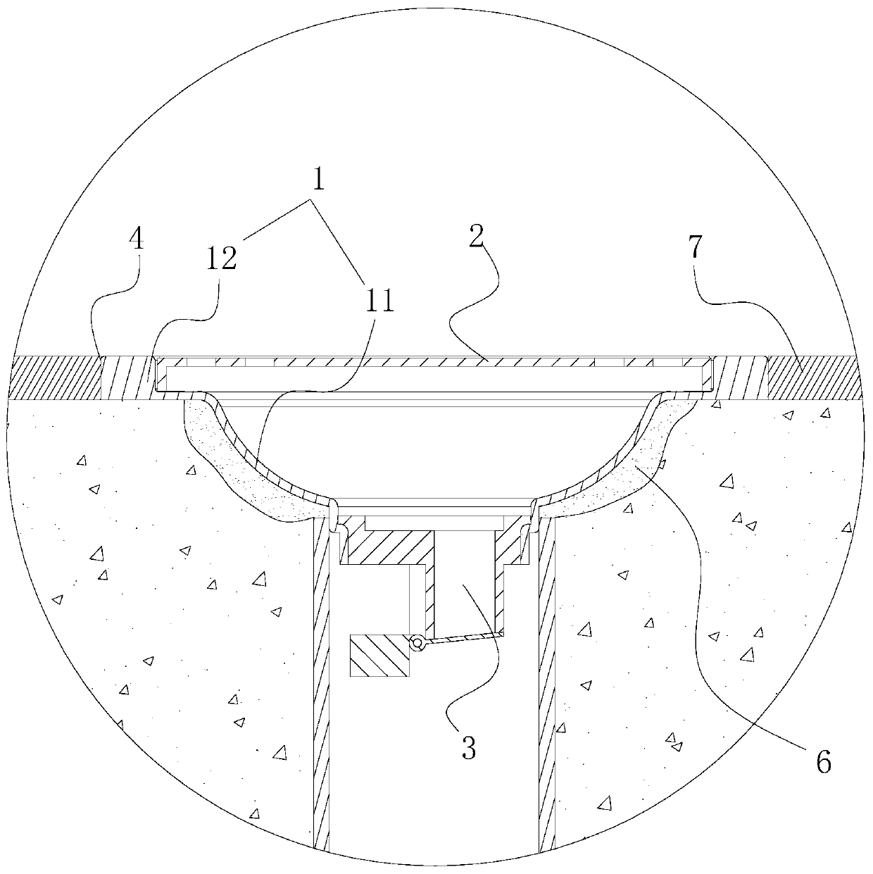
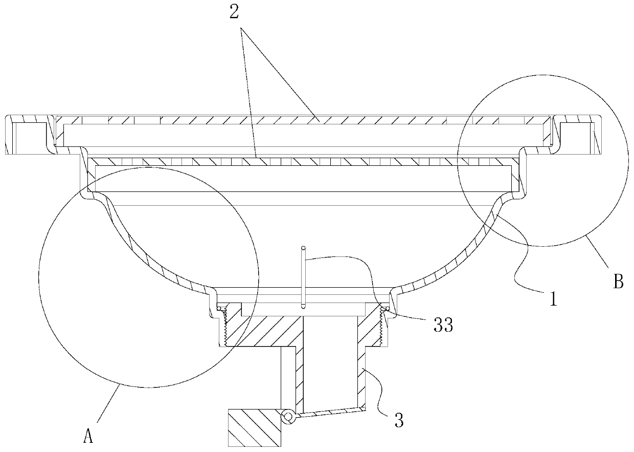
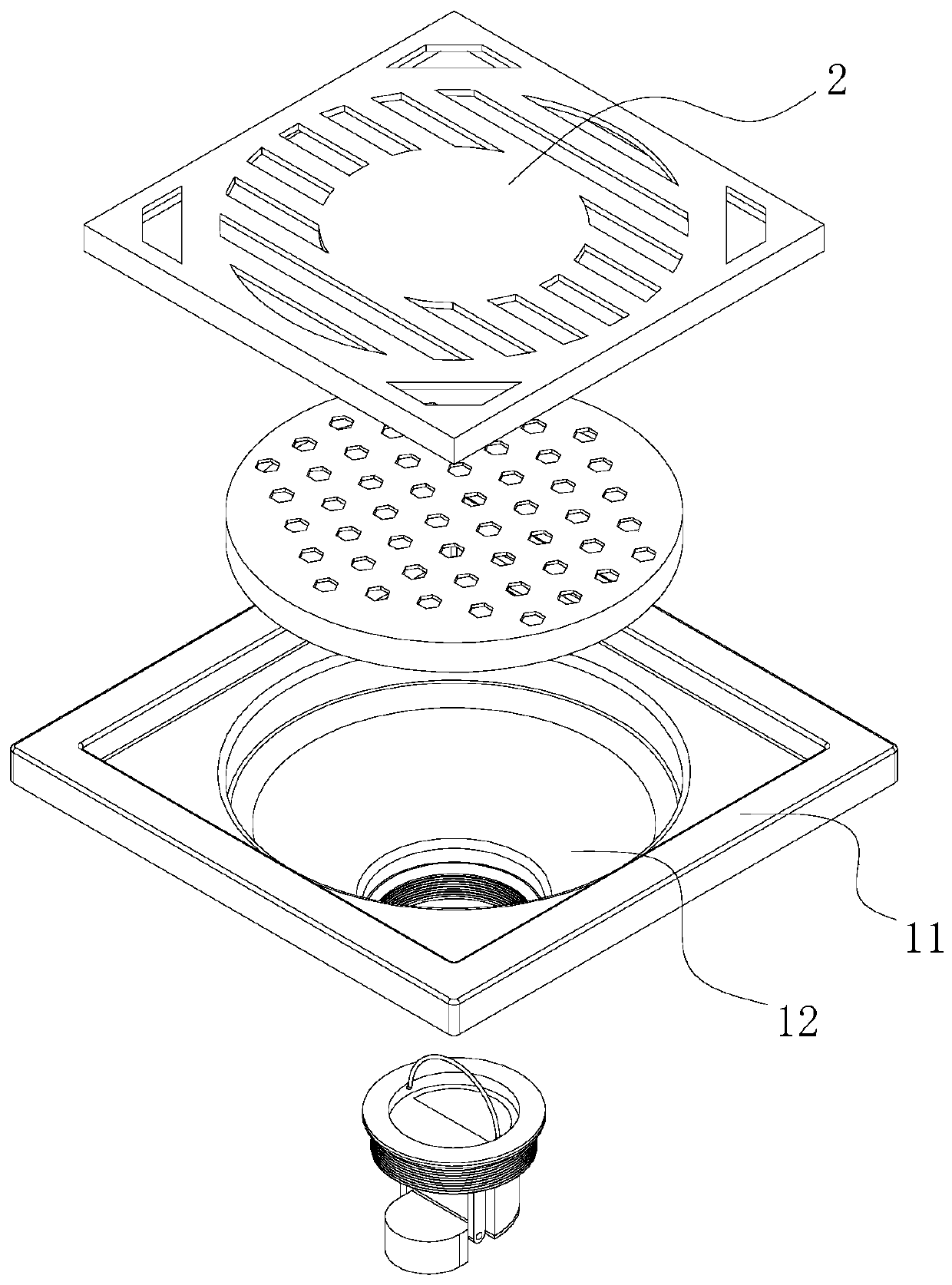
[0048] A floor drain, combined with figure 2 and image 3 As shown, it includes the floor drain body 1 whose main connection function and the lower end communicate with the drainage pipe, two pieces of grate plate 2 which are placed in the upper opening of the floor drain body 1 in sequence from top to bottom to intercept foreign matter, and installed on the lower end of the floor drain The blocking mechanism 3 used to prevent sewage and foreign matter from rushing back out of the floor drain from the drainage pipe.

[0049] like image 3 As shown, the floor drain body 1 includes a funnel-shaped main body 11 for installing the blocking mechanism 3 and an installation portion 12 arranged on the upper end of the main body 11 for installing various grate plates 2 .

[0050] combine image 3 and Figure 4 As shown, the body 11 includes a connecting ...


PUM


Abstract

The invention discloses a floor drain, and a mounting structure and production process thereof, and relates to the technical field of floor drains. The technical problem that the material cost advantage is too low is solved. According to the technical key points, the floor drain comprises a floor drain body, a grate plate and a blocking mechanism, wherein the floor drain body comprises a body anda mounting part arranged at the upper end of the body, wherein the mounting part comprises a first flanging part, a second flanging part, a third flanging part and a fourth flanging part. The floor drain has the advantages of reducing the material cost.

Description

technical field [0001] The invention relates to the technical field of floor drains, in particular to a floor drain, its installation structure and production process. Background technique [0002] The floor drain refers to the drainage device connected between the ground and the drainage system. It is an important interface connecting the drainage system and the indoor ground. As an important part of the drainage system in the house, its performance directly affects the quality of the indoor air, and it is important for the bathroom. Odor control is very important. [0003] Such as figure 1 As shown, the existing floor drains are generally installed on the floor drain body 1 in the ground concrete structure of the bathroom, and are arranged inside the floor drain body 1 to prevent anti-gas phenomenon (the sewage in the drainage pipe will produce peculiar smell, and the peculiar smell is directly distributed through the floor drain body The phenomenon is anti-gas phenomeno...

Claims


Application Information

Patent Timeline
Patent Type & Authority Applications(China)
IPC IPC(8): E03F5/04E03F5/06E03F5/042E03F5/14
CPCE03F5/0407E03F5/041E03F5/042E03F5/06E03F5/14E03F2005/0416
Inventor 林生盛
Owner 厦门盛腾发工贸有限公司
Why Eureka
Try Eureka